Make Your Own Fritzing Parts
 HelloTechie
What is Fritzing?

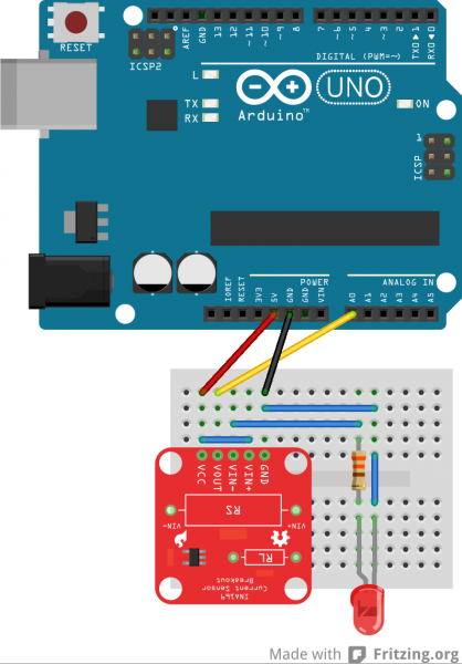
Fritzing is a great open source tool for anyone to teach, share, and prototype their electronic projects! It allows you to design a schematic, and thus a part, which can then be added to very professional-looking wiring diagrams. You can even design your own PCBs and have them fabricated from the files you design. Here at SparkFun, we use Fritzing in the classrooms, our hook-up guides, and any other place we need to show how to hook-up our boards to other hardware.
The awesome thing about Fritzing is that you can make your own Fritzing parts for your project and share with the community! This tutorial is going to go over how to make a custom Fritzing part in the Fritzing (New) Parts Editor, starting from the beginning.
Do You Need to Make a Custom Fritzing Part?
Fritzing comes with tons of electronic parts already installed with the software. SparkFun also has a Fritzing Github repo for housing parts we've created not already in Fritzing. Before creating your own part, double check to see if it exists in those two locations or if another Fritzing user already made the part you need on the Fritzing forum. It will save you a lot of time if the part is already made! However, if you're certain that the part you need doesn't live in Fritzing land already, read on!
Suggested Reading
This tutorial assumes that you are already familiar with Adobe Illustrator, Inscape, or both. Using these programs is beyond the scope of this tutorial. If you need more info on how to use eithwer of these programs, their respective websites should have lots of tutorials and guides on how to get started with vector graphics. If that fails, there's always Google.
Here are other related tutorials you may want to check out before reading this one:
Download and Install
You will need to download and install the following software in order to follow along and make your own custom Fritzing part.
Please Note: If you only need to make a basic IC, Fritzing (New) Parts Editor allows you to make custom ICs easily, and you won’t need to download a vector graphic editor. You can still follow along, since this tutorial will be building off a custom IC in the Fritzing (New) Parts Editor.
Fritzing
Go to the download page on the Fritzing site to download the latest Fritzing version for your OS. Find where you want to put the Fritzing application on your hard drive, and unzip the Fritzing folder in that location.
Vector Graphics Editor
There is a lot of different types of vector graphics editors out there. The vector graphics editors we use here at SparkFun are Adobe Illustrator and Inkscape. Choose the one you are the most familiar and comfortable with. If you don't have a vector graphics editor, Inkscape is a great open source choice, and it is free.
Inkscape

Go to the Inkscape download page and download the appropriate Official Release Package for your computer.
Windows Users: Double click on the executable. Follow along the Inkscape Setup Wizard.
Mac OS X Users: Follow along the newest instructions on the Inkscape site.
Adobe Illustrator

Adobe Illustrator is not free, but if you already have the Adobe Creative Cloud you can download it. You can also purchase an Illustrator monthly membership.
Please Note: We have no affiliation with Adobe and are only promoting Illustrator because it is a great piece of software that works well for what we need in this tutorial.
Other Downloads
Fritzing Fonts and Templates
Fritzing uses the OCR-A font for ICs. For all the other parts you can use OCR-A and Droid Sans fonts. Fritzing has fonts and templates available for download on their site. You will need to download Fritzing's Graphic Standards to follow this tutorial. Go to their template download page, and download the Fritzing's Graphic Standards folder. After you download their zip file, you will need to make sure to unzip the folder, and place anywhere on your computer. You will want to install the fonts on your computer.
SparkFun Fritzing Example Templates
This tutorial will reference the SparkFun Fritzing Example Templates a lot. If you are making a Fritzing part for a SparkFun board or want a starting point, download this set of example templates from the SparkFun Fritzing Parts Github repo. The SparkFun Fritzing templates will have this tutorial's example, SparkFun T5403 Barometer Breakout SVG, files to compare and work with.
Breadboard View
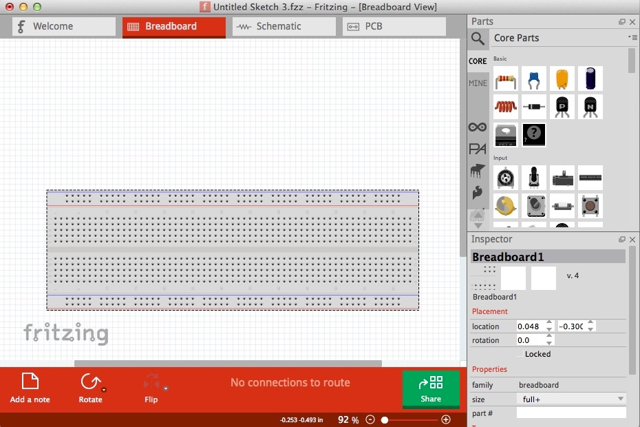
When the Fritzing starts up, you should be in the Welcome view. You will want to go to Breadboard view.
There is two main steps you will need to do in Breadboard view. First, create your breadboard SVG, and upload it. Fritzing prefers using SVG format, so your images look great when you are zoomed in and out! Second, you'll need to change the connector pins.
Please note: If you are only making a basic IC you can skip to Editing Breadboard View section of this tutorial.
Fritzing Graphic Standards
On the Fritzing website, there are a lot of graphic standards to follow. It is a great idea to follow the graphic standards that way your parts match other Fritzing parts.
Templates
When making you part, it is recommended to start from a template. Have an image of the part to refer to, so, when making your SVG files, the process will go faster.
Tip: If you are making a custom Fritzing part for a board you made in EAGLE, you can download an ULP that converts boards to SVG. This way you can have an accurate SVG of your EAGLE board for a reference. You can find EAGLE ULPs on the Cadsoft site.
It is time to make your graphic for the Breadboard view!
Create a New Part
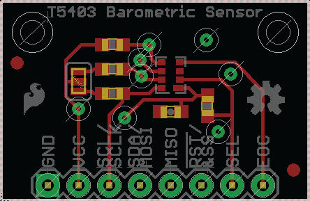
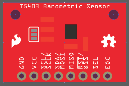
For this tutorial, we are going to create a Fritzing part for the SparkFun T5403 Barometer Breakout.
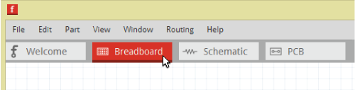
Open the Fritzing application. You should see tabs for Welcome, Breadboard, Schematic, and PCB towards the top of the program. Click on Breadboard button to make sure you are in the Breadboard view.
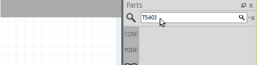
Check for Pre-made Parts
If you are just updating a board in Fritzing, first check to see if there is a part that is closely related to the Fritzing part you are trying to create. You can type the part's name into the search bar.
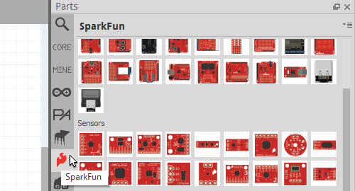
You can also look in the different sections of the Fritzing's Parts window for a similar part.
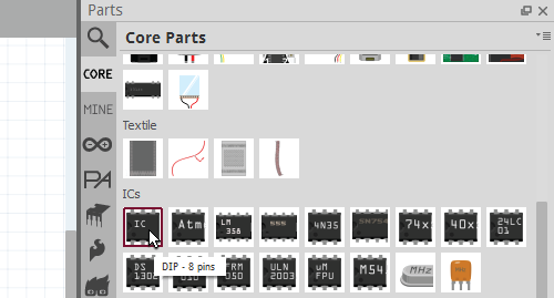
Using an IC as a Starting Point
If there is not a part like the one you are trying to make, using an IC as a base is a great place to start. Click on the CORE tab in the Part Window. Scroll down until you see the ICs. Under the ICs section, click and drag the IC icon onto the Breadboard window.
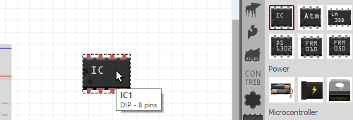
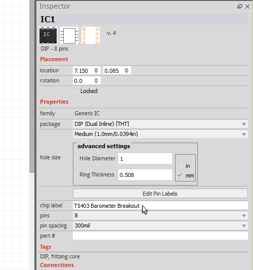
Changing the Name of the IC
Look for the IC properties in the Inspector window on the right. Change the name of the IC to your part's name. Then, change the number of pins needed for the board or part in the pins section. For the SparkFun T5403 Barometer Breakout, we need 8 pins. You will see the IC, in the Breadboard view, change to your part’s name.
Fritzing (New) Parts Editor
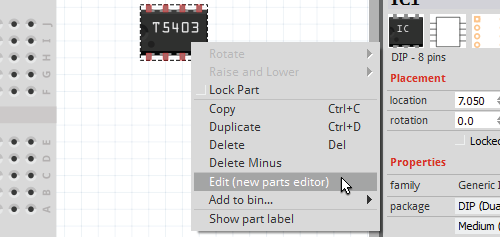
Right-click the IC in the Breadboard window, and select Edit (new parts editor). The Fritzing (New) Parts Editor should pop up.
There are 6 main sections of the Fritzing (New) Parts Editor in which you will need to make changes. Those are:
- Breadboard
- Schematic
- PCB
- Icon
- Metadata
- Connectors
There really isn't an order you need to follow. After making a couple different custom parts you will probably end up starting in one view before the others. In this tutorial, we're just going to go down the list.
Author note: I found, for boards with a large number of pins, that starting off in the Connectors view saves a little bit more time, since you can go down the list to name the connector pins faster.
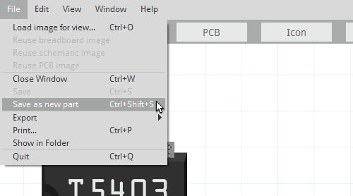
Before you continue on, it is a good idea to save as a new part first. If you need to stop anytime when making the custom part, you can come back to it in the future. Go to File. Then, select Save as new part.
You can choose to name the prefix if you want.
Let's continue on to Breadboard view!
Custom Breadboard SVG
Create a File
Open up your vector graphics editor and create a new file. The image size of the file should be the same size of your board. The SparkFun T5403 Barometer Breakout size is 1" x 0.650". You are going to want to save the file with a good naming convention, since you are going to end up needing 3 different svg files when creating your Fritzing part.
Illustrator Users: You can save by going to File->Save As, saving as a SVG, and hitting Save.
For this example the Breadboard SVG is named: SFE_T5403_Barometer_Breakout_breadboard.svg
Use Templates as References
To compare the different layers and groups, you can open up the Fritzing BreadboardViewGraphic_Template.svg file found in the Fritzing Fonts and Template folder you downloaded earlier. You can also open the example SparkFun T5403 Barometer Breakout breadboard SVG template file from the SparkFun Fritzing Parts Github repo.
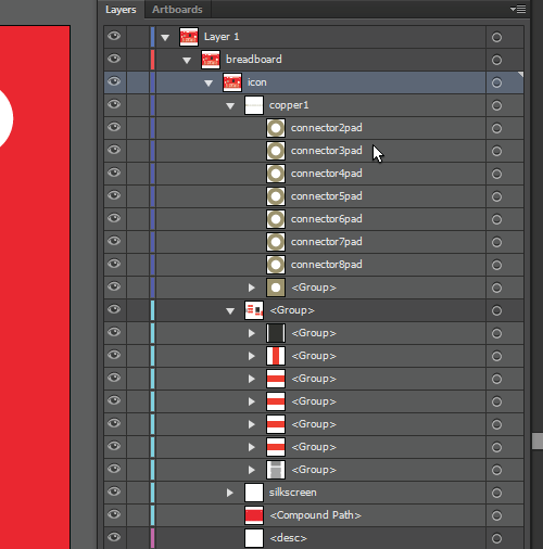
You can see with the example templates how you can kept the layers organized. For the SparkFun T5403 Barometer Breakout, there is a “breadboard” group. Inside that breadboard group it will have the group of parts, copper layers, silkscreen group, and the board path.
Tips for Making Your Custom Breadboard Graphic
You are now able to create your custom part’s breadboard graphic. Here are some helpful tips!
Follow the Fritzing Graphic Standards
Here are some main color standards for Breadboard images:
To keep with the Fritzing graphics standards, you are going to want to make the copper contacts the copper/tinned color.

If you have legs on any of your parts on your board, the color to use is grey.

SparkFun Red is:

Keep It Simple
The great thing with Fritzing is you can make your board as simple or as complex as you want. Since SparkFun is always trying to make our products better with revisions and have a lot of boards, it is easier and faster for us to not included certain details, like traces or every component, on our boards. That way if there is a new change with the board, like a resistor value change, we don't have to go in and change that resistor in the Fritzing part. Focusing more on the important components, like ICs, might be a better way to spend your time. It will still look nice, but less work!
Use Components That Already Exist
If you need an SMD LED on your board that is already in Fritzing, go ahead and use it! This will save you time and keep the all the Fritzing parts having the same look and feel. If you create a custom board with components that others can use, you can share them on the Fritzing site, so others can use too! Make sure to organize the component graphics nicely in the vector graphics editor you are using, so the parts are easy to find when using on future boards.
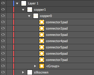
Name Connector Pins in Copper Groups
Naming your connectors will be a huge time saver. For the SparkFun T5403 Barometer Breakout example, under the copper group, each connector is named connector#pad.
Use the ORC-A or Droid Sans Fonts.
Stick with the Fritzing fonts to kept all Fritzing parts looking alike. It is suggested that the standard font size is 5pt. However, there will be times you won't have space for smaller boards. You won't want to go lower then 3pt, because it starts to become harder to see without zooming in. On the Fritzing site they mention using black as the font color. Whatever your silkscreen color is tends to look better. For this example we are using white, since that is the breakout board's silkscreen color and it is easier to read against a red background.
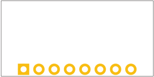
Create a Compound Path to Make Board Openings See-Through
Illustrator Users: Create a path in the size of your PCB. For the SparkFun T5403 Barometer Breakout, you can use the rectangle tool to make a 1" x 0.650" rectangle. Then, make paths where you have openings in your board. For example, you can use the ellipse tool, under the rectangle tool, to make perfect circles where there are openings for stand-offs and connector pins. Select all the hole opening layers and the bottom PCB layer.
Next, go to Object->Compound Path->Make. You should now have a compound path, and you will be able to see through the openings in Fritzing.
Save
Make sure to Save as SVG again once you are done creating your custom board! Now, you can continue on to Editing Breadboard View.
Breadboard View - Parts Editor
Load Image
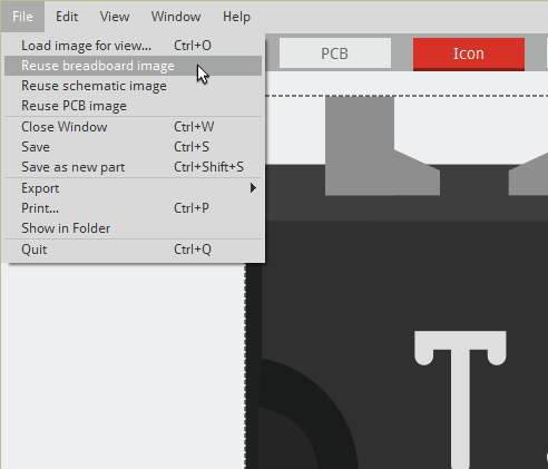
After you created your custom breadboard image, you will want to load the breadboard SVG in the Fritzing (New) Parts Editor. First, go back to the Fritzing (New) Parts Editor and click the Breadboard button to get into the Breadboard view. Go to File->Load image for view.
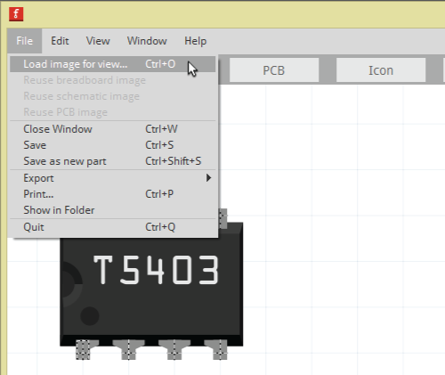
Next, you will select the breadboard SVG you just created and hit Open. The graphic should be now in the Fritzing (New) Parts Editor.
Connectors
When working in the main Fritzing application, you connect different Fritzing parts with colored wires to show how the parts connect to one and another. In order for Fritzing to know where connector pins are on a board or part, you will need to tell Fritzing where those connectors are.
Name and Description for Connector Pins
For the Breadboard view, the Connectors window will be on the right side of the Fritzing (New) Parts Editor. Select a pin to change the name of the pin and to add a description.
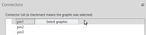
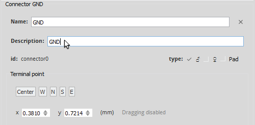
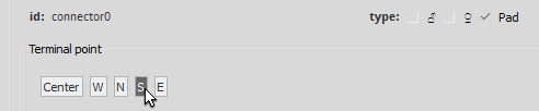
Select the Connector Pin's Graphic
Click on the Select graphic button on the right of your connector pin's name. Then, click on the connector pin's graphic. This will set the Anchor point. The Anchor point is the location where the wire connects to that connector. By default the Terminal point will show up in the middle of the selected graphic. If you want to move the Terminal point, you are able to click on the Terminal point and hold to move. You can also change the Terminal point by clicking on either “Center”, “W”, “N”, “S”, or “E” in the Connectors window.
Change Connector Type
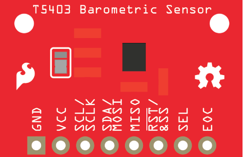
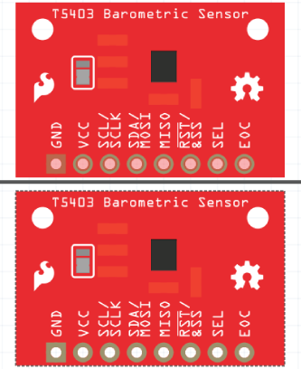
Change the type of connector in the Connectors window. You can choose from male, female, or pad. For the SparkFun T5403 Barometer Breakout, all the connector pins are female.
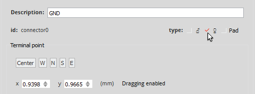
In the image below, you can see the differences between setting the connector type as male vs female.
Repeat for All Connector Pins
Name, select the appropriate graphic, and change the connector type for all your connector pins. You can also set Internal Connections in the Connectors window.
Schematic View
Custom Schematic SVG
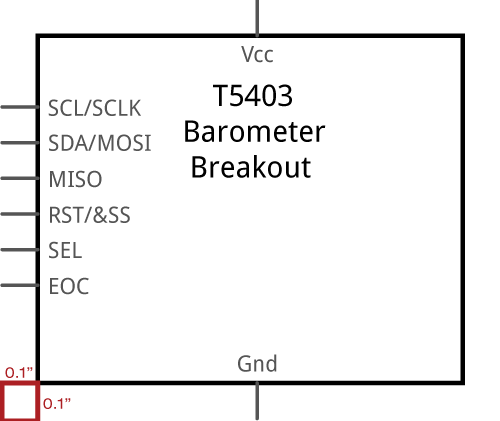
Go back to either Illustrator, Inkscape, or the vector graphic editor you are using. Open up the Fritzing's SchematicViewGraphic_Template.svg in the downloaded Fonts and Templates folder. You can also open the example SparkFun T5403 Barometer Breakout schematic SVG template file from the SparkFun Fritzing Parts Github repo.
When editing the schematic to match your board, you will want to make sure each connector pin is shown. You will want to change the pin labels to match the connector pin names. Depending on your part, you might have to resize the template schematic. Make sure there is 0.1” space between the main part symbol square and the edge of the outer pins.
Save SVG
You will want make sure to save as a new SVG. Remember to have a naming convention that will be easy to tell the difference between the other SVG files you are creating for your Fritzing part.
Editing Schematic View in Parts Editor
Load SVG
Go back to the Parts Editor, and click on the Schematic button to go to the Schematic view. Go to File->Load image for view. Next, you will select the schematic SVG you just created, and click Open. The part should be now in the Fritzing (New) Parts Editor.
Set Connector Pins
If you look at the Connectors window on the right side, you will notice that your pin names are already there. When you make a change to the connector pin's name and description in either Breadboard, Schematic, PCB, or Connectors view, the Parts Editor will automatically change the connector pin's name and description for the other views. Also, the connector type (male, female, or pad) will still be the same.
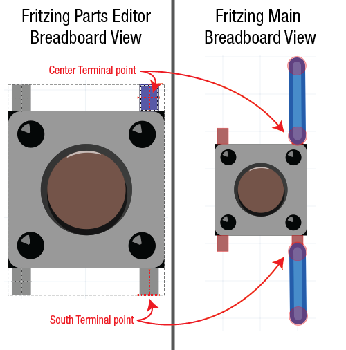
Just like you did in Breadboard view, you will still need to select a graphic for each pin. Click on the 'Select graphic' button, and choose the appropriate graphic for that pin. For the Schematic view, you are going to want to change the Terminal point, so the connecting wires are connecting at the furthest point.
The easiest way to do this is make sure the connector pin’s graphic is still selected, and change the Terminal point in the Connectors window. For the GND graphic, the Terminal point is moved to the south end by clicking on “S”.
Repeat for All Connectors
After you update all your connector pins you can move on to Editing in PCB view.
PCB View
Making custom PCB SVG
Go back to either Illustrator, Inkscape, or the vector graphic editor you are using. When making a custom PCB SVG, the main image groups you will need are copper (which will have all your connector pads) and silkscreen.
Create the PCB Graphic
You can either start fresh when creating a PCB SVG, modify your custom breadboard SVG, or edit the Fritzing's PCBViewGraphic_Template.svg in the downloaded Fonts and Templates folder. For this example, the custom breadboard SVG was modified, and the file was saved as a new SVG called SFE_T5403_Barometer_Breakout_PCB.svg.
Make Sure to have Two Copper Groups
When setting up your layers, make sure to have two copper groups. All of your connector layers should be in the copper groups. When you do this, Fritzing will know that the component has the copper connectors on both sides of the PCB.
Make Sure the Connector Pins' Spacing is Accurate
It is important to have the PCB connector pins match accurately with your board and to have the appropriate spacing between pins. Fritzing offers a PCB Fab services. If you or other Fritzing users want to use that service with your custom part, you will want to make sure your PCB view is accurate.
Graphic Standards
Instead of the connector pins being a copper/tinned green color, the PCB view connector pins are the "copper" color:

The main changes made from the custom breadboard SVG is that the main groups are copper and silkscreen. The silkscreen will still be white.
Editing PCB View in Parts Editor
Go back to the Parts Editor, and click on the PCB button to get to PCB view. Go to File->Load image for view. Next, you will select the PCB SVG you just created, and click Open. The part should be now in the Fritzing (New) Parts Editor.
Update Connector Pins
Select the appropriate graphics for each connector pin, just like you did in Breadboard and Schematic view.
Icon View
Reuse a Past Graphic
Go to the Fritzing (New) Parts Editor, and click on the Icon button to get to Icon view. The great thing about Icon view is that you can reuse your breadboard, schematic, or PCB SVG for the icon image, so there is no need to make a new image! All you need to do is go to File and select what image you want to reuse. For the SparkFun T5403 Barometer Breakout, the Icon view reuses the breadboard image. The breadboard image should show up.
Great Scott! You are now done with Icon view!
Metadata
Go to Metadata View
Go to the Parts Editor, and click the Metadata button to go into Metadata view. The Metadata is where you will add all the important information about your part!
Different Sections in the Metadata View
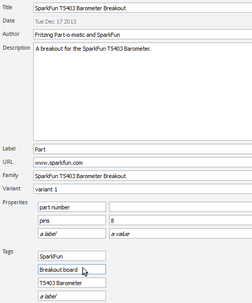
Title: Pretty self-explanatory. This is going to be the name of your part.
Date: The date entry is locked in Fritzing. The date should show the date you are creating the part. If you update the part later down the road, the date will be changed to the current date of the last update.
Author: You will want to put your name in here, so, if you share your part with the Fritzing community, they know who made the part.
Description: Description should included anything that is important about the board, such as operating voltage.
Label: The Label is shown in Schematic view and makes it easier to tell which part you have selected. For the SparkFun T5403 Barometer Breakout, the Label is changed to Part. The reason for that is, because Part is fairly small and the SparkFun T5403 Barometer Breakout name is already on the schematic graphic itself. It is up to you what you want to label your part!
URL: Consider posting the url of the part, so anyone can get more information about your part.
Family: If you have a part that comes in different colors, chip packages, etc, you will want them to be in the same Family. For example if you have a through-hole LED that comes in different colors, all the different colors of the same LED will be in the same family.
Variant: When creating a brand new part, you want to make sure the Variant is 1. When you do revisions in the future, it will change the next revision to Variant 2 if it is in the same family.
Properties: A place to put important details like part numbers, pin spacing, and etc.
Tags: Use tags that can be found easier and best describe your part in as few words as possible.
Connectors View
Go to Connectors view
Go to the Parts Editor, and click the Connectors button to go into Connectors view. In the Connectors view you are able to do the following:
- Change the number of connectors
- Set connector type
- Set the connector pins as Through-hole or SMD
- Name connector pins
- Add connector pin descriptions
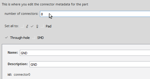
You shouldn't need to change anything in the Connectors view, since you already filled out all the information in the other views. If you need to make any last minute changes, now you can. Keep in mind, if you change the number of connectors here, you will need to go back and update Breadboard, Schematic, and PCB views.
Save
Now you can save your part! Go to File>Save
Continue on to exporting part!
Exporting New Part
Quality Check in Fritzing Application
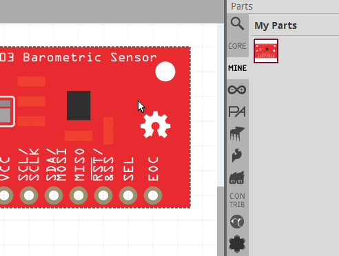
It is time to check out your new Fritzing part in the main Fritzing application. When you Saved As new part in the Fritzing (New) Parts Editor earlier, the part automatically shows under the My Parts label in the MINE tab in the main Fritzing application.
Before exporting your new custom part, you will want to check if each view looks good. Make sure you are in the main Fritzing application and not the Fritzing (New) Parts Editor. Go to Breadboard view by clicking on the Breadboard button at the top. In the Parts window, on the right side, make sure you are in the MINE tab. You should see your new part. Click and drag the board on the Breadboard view.
Double check if the pins are named correctly and are working properly. Do the same in the Schematic and PCB view. Once you have done a quality check, you can export the part.
Export part
Right click on the new part’s icon in the My Parts window and select Export Part. Save out your Fritzing part.

Resources and Going Further
Remember to check out the Fritzing software or the Fritzing forums to see if the part has been made. Or you can check out our SparkFun parts library in our repo. Also, check out Fritzing's landing page for creating custom parts to see how others create parts in Fritzing, graphic standards, templates, naming conventions, and methods of formatting your file.
- Fritzing.org
- GitHub Repo - SparkFun parts library that are not included in the Fritzing software library
Contribute to Fritzing
Now that you have your part done, you are able to connect with other Fritzing parts. You can share your part or a project tutorial on the Fritzing site. There are many more ways to contribute to the Fritzing community! Check out the Fritzing Support Us page for even more ways to support Fritzing.
Large Batches of Fritzing Parts?
If you are a developer that uses EAGLE or someone who is investing a lot of time in making Fritzing parts, the Fritzing team has open sourced a toolkit to make the SVG files from EAGLE .brd files. It is highly recommended that you check out if you are creating batches of SVG board files ready for Fritzing. They have the source code for to convert Eagle to Fritzing in a Fritzing GitHub repo.
Further Reading
At SparkFun, we use Fritzing at a lot in our Learn tutorials. Check out how we use Fritzing in different tutorials to show how to connect different parts together. Here are some tutorials that uses Fritzing in the hookup section:
If you want to learn more about designing your own PCBs with other software, visit these tutorials:
Looking for more information about Fritzing? Check out these related blog posts:
For vector images of parts, try the Electronic Graphics Resources so that you do not have to make a part from scratch.