Make Your Own Fritzing Parts
 HelloTechie
Custom Breadboard SVG
Create a File
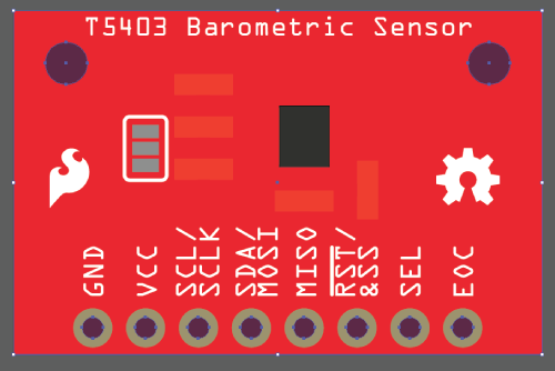
Open up your vector graphics editor and create a new file. The image size of the file should be the same size of your board. The SparkFun T5403 Barometer Breakout size is 1" x 0.650". You are going to want to save the file with a good naming convention, since you are going to end up needing 3 different svg files when creating your Fritzing part.
Illustrator Users: You can save by going to File->Save As, saving as a SVG, and hitting Save.
For this example the Breadboard SVG is named: SFE_T5403_Barometer_Breakout_breadboard.svg
Use Templates as References
To compare the different layers and groups, you can open up the Fritzing BreadboardViewGraphic_Template.svg file found in the Fritzing Fonts and Template folder you downloaded earlier. You can also open the example SparkFun T5403 Barometer Breakout breadboard SVG template file from the SparkFun Fritzing Parts Github repo.
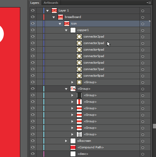
You can see with the example templates how you can kept the layers organized. For the SparkFun T5403 Barometer Breakout, there is a “breadboard” group. Inside that breadboard group it will have the group of parts, copper layers, silkscreen group, and the board path.
Tips for Making Your Custom Breadboard Graphic
You are now able to create your custom part’s breadboard graphic. Here are some helpful tips!
Follow the Fritzing Graphic Standards
Here are some main color standards for Breadboard images:
To keep with the Fritzing graphics standards, you are going to want to make the copper contacts the copper/tinned color.

If you have legs on any of your parts on your board, the color to use is grey.

SparkFun Red is:

Keep It Simple
The great thing with Fritzing is you can make your board as simple or as complex as you want. Since SparkFun is always trying to make our products better with revisions and have a lot of boards, it is easier and faster for us to not included certain details, like traces or every component, on our boards. That way if there is a new change with the board, like a resistor value change, we don't have to go in and change that resistor in the Fritzing part. Focusing more on the important components, like ICs, might be a better way to spend your time. It will still look nice, but less work!
Use Components That Already Exist
If you need an SMD LED on your board that is already in Fritzing, go ahead and use it! This will save you time and keep the all the Fritzing parts having the same look and feel. If you create a custom board with components that others can use, you can share them on the Fritzing site, so others can use too! Make sure to organize the component graphics nicely in the vector graphics editor you are using, so the parts are easy to find when using on future boards.
Name Connector Pins in Copper Groups
Naming your connectors will be a huge time saver. For the SparkFun T5403 Barometer Breakout example, under the copper group, each connector is named connector#pad.
Use the ORC-A or Droid Sans Fonts.
Stick with the Fritzing fonts to kept all Fritzing parts looking alike. It is suggested that the standard font size is 5pt. However, there will be times you won't have space for smaller boards. You won't want to go lower then 3pt, because it starts to become harder to see without zooming in. On the Fritzing site they mention using black as the font color. Whatever your silkscreen color is tends to look better. For this example we are using white, since that is the breakout board's silkscreen color and it is easier to read against a red background.
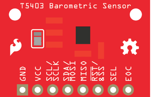
Create a Compound Path to Make Board Openings See-Through
Illustrator Users: Create a path in the size of your PCB. For the SparkFun T5403 Barometer Breakout, you can use the rectangle tool to make a 1" x 0.650" rectangle. Then, make paths where you have openings in your board. For example, you can use the ellipse tool, under the rectangle tool, to make perfect circles where there are openings for stand-offs and connector pins. Select all the hole opening layers and the bottom PCB layer.
Next, go to Object->Compound Path->Make. You should now have a compound path, and you will be able to see through the openings in Fritzing.
Save
Make sure to Save as SVG again once you are done creating your custom board! Now, you can continue on to Editing Breadboard View.