Making Music with the FreeSoC2
 Nick Poole
Introduction
The FreeSoC2 is an excellent platform for playing with the capabilities of Cypress PSoC devices. I had never touched a PSoC before this project, so I wasn't sure exactly what I was getting into. Turns out, they're a pleasure to work with. Whenever I get a chance to play with a new technology, I like to build a simple musical instrument. Why? Because even the most basic keyboard synthesizer incorporates important concepts like pushbutton input and output, signal generation, signal switching and timing. Building this keyboard gave me a pretty good window into the FreeSoC2 and helped me get a hang of using the PSoC Creator software.
Materials Required
To follow along with this tutorial, you will need the following:
Suggested Reading
Before you embark on this build, it's a good idea to check out this FreeSoC2 Introduction so you have some familiarity with the hardware. Here some other tutorials you may find handy:
Hardware Overview
Before I show you what's going on in PSoC Creator, let's take a look at what I have hooked up to the FreeSoC2 board:
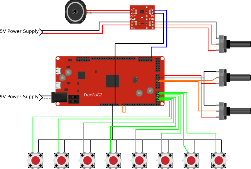
The diagram above lays out the connections so that you can trace them visually, but here's how it breaks down:
- Pins 5.0 - 5.7 are connected through eight pushbuttons to ground.
- Pins 3.6 and 3.7 are connected to the wipers of two potentiometers.
- Pin 4.1 is connected to the input of the Mono Amp Breakout board.
- A speaker is connected to the output side of the Mono Amp Breakout board.
- The Mono Amp Breakout and FreeSoC2 board are powered using separate power adapters in order to avoid introducing noise to the amp.
PSoC Schematic
Now that the FreeSoC board is wired up, let's open up the PSoC Creator software and take a look at the project. You can get the project files from the GitHub Repo here. When you open up the schematic view, you'll see the whole project at once:
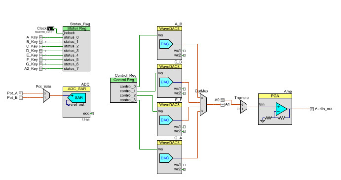
As you can see, it's split up into a few discrete modules with inputs on the left and outputs on the right. The easiest way to understand what's happening here is to break it down by section:
Digital Inputs
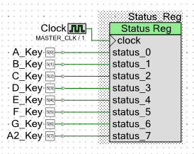
You'll remember from the hardware overview that we connected 8 pushbuttons to a row of analog pins on the FreeSoC board. In order to read the status of these buttons, we need to route them internally to something called a status register. The status register accumulates the status of up to 8 digital pins and allows you to fetch them using simple function calls in the firmware. Every time we call Status_Reg.Read() it will return an 8-bit number that represents whether each pin is high or low.
Analog Inputs
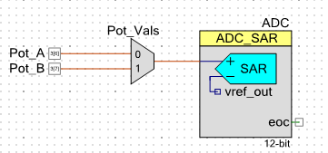
To read the potentiometers, we'll need to set up an ADC. If you're familiar with the ADC on the Arduino, the SAR on the FreeSoC is very similar. There aren't enough separate ADCs to set up one for each analog input, which would be a waste of resources anyway, so we need to multiplex the input. The component labeled Pot_Vals is a 2-channel analog multiplexer that allows us to connect either of the two potentiometers to the ADC. To get a reading from a specific potentiometer, the first thing we need to do is call Pot_Vals_Select() to connect the right pin to the ADC. Then we start the ADC conversion and finally retrieve the ADC result.
Signal Generator and Output
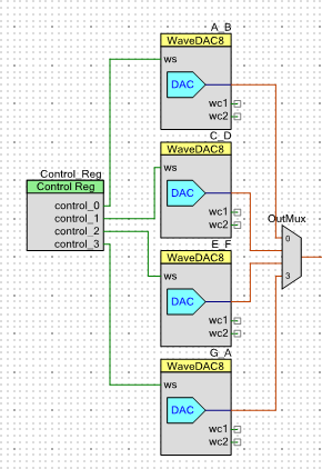
This is the heart of the project, and it's based on an awesome component called the WaveDAC. The WaveDAC combines a waveform generator with a digital-to-analog converter so that all you need to do in order to make an analog waveform is define the waveshape and the frequency. Each WaveDAC can store two predefined waveshapes that can be selected during runtime by switching the digital input labeled ws.
Because each WaveDAC will only store two waveforms, we need to stack a few of them to get 8 distinct tones. Also, because they're constantly generating a tone we need a way of switching between the WaveDACs so the outputs are piped into a multiplexer.
Finally, the WaveDAC ws lines are all tied to a control register. A control register is similar the status register except that it works as an output instead of an input. By making simple function calls in the firmware, we can control a number of digital signals during runtime.
Gain and Tremolo
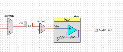
The last two stages before the final output are the tremolo, which is simply a multiplexer with one input left floating, and the variable gain, which is achieved using a programmable gain amplifier.
You'll notice that the output from the signal generator stage doesn't go directly into the Tremolo multiplexer. This is because PSoC Creator doesn't allow you to connect the output of one multiplexer to the input of another. We got around this by bridging two analog pins together and sending the signal through.
The tremolo effect is achieved by switching the multiplexer back and forth between two channels, one is connected to the output of the signal generator stage and one is left unconnected. By controlling the delay between channels, we can control the rate of the tremolo.
The gain control is achieved by sending the output from the tremolo stage into a Programmable Gain Amplifier or PGA. The PGA amplifies the incoming signal by a factor set during runtime by the firmware.
To find out how all of this works together, we'll need to tuck into the firmware...
Firmware
Now that the hardware is all hooked up and the PSoC device is configured, it's time to look over the firmware. The code isn't very complex but we'll cut it into sections so that we can break it down by function, starting with the initializing code:
language:c
#include <project.h>
#include <stdbool.h>

int main()
{
/* initialization/startup */

A_B_Start();
C_D_Start();
E_F_Start();
G_A_Start();
OutMux_Start();
Pot_Vals_Start();
ADC_Start();
Tremolo_Start();
Amp_Start();

uint8 InputReg;
int16 Pot_A_val;
int16 Pot_B_val;

Amp_SetGain(Amp_GAIN_01);
The initialization portion of the code is fairly straight-forward. The first few lines are procedure calls to start each of the components from the schematic. Then we set up a few variables to keep track of our status register and potentiometer values. And finally, we need to initialize the programmable gain amplifier.
language:c
for(;;)
{
    Pot_Vals_Select(0);
    CyDelay(25);
    ADC_StartConvert();
    ADC_IsEndConversion(ADC_WAIT_FOR_RESULT);
    Pot_A_val = ADC_GetResult16();

    Pot_Vals_Select(1);
    CyDelay(25);
    ADC_StartConvert();
    ADC_IsEndConversion(ADC_WAIT_FOR_RESULT);
    Pot_B_val = ADC_GetResult16();


    InputReg = Status_Reg_Read();
Here we've started the main code loop by reading all of our inputs. For each of our potentiometers, we first select the correct channel on the ADC multiplexer. Then we need to start the conversion which is quick but not instantaneous so before we retrieve the results we need to wait for the conversion to end. The procedure call ADC_IsEndConversion(ADC_WAIT_FOR_RESULT) essentially busy-waits until the ADC conversion is complete and the results are ready to retrieve.
The digital inputs are easier to handle, all we need to do is call Status_Reg_Read() which returns an 8-bit number where each bit represents the status of one input.
language:c
switch(InputReg){

 case 1:
    Control_Reg_Write(0); //0000
    OutMux_Select(0);
 break;

 case 2:
    Control_Reg_Write(1); //0001
    OutMux_Select(0);
 break;

 case 4:
    Control_Reg_Write(1); //0001
    OutMux_Select(1);
 break;

 case 8:
    Control_Reg_Write(2); //0010
    OutMux_Select(1);
 break;

 case 16:
Control_Reg_Write(2); //0010
OutMux_Select(2);
 break;

 case 32:
Control_Reg_Write(4); //0100
OutMux_Select(2);
 break;

 case 64:
Control_Reg_Write(4); //0100
OutMux_Select(3);
 break;

 case 128:
Control_Reg_Write(8); //1000
OutMux_Select(3);
 break;

 default:
    OutMux_DisconnectAll();
 break;

}
This switch/case statement selects the correct output channel and waveshape depending on the key that's being pressed. Two function calls are required to play a tone: first we need to write to the control register in order to select the proper waveshape on the proper WaveDAC and secondly, we need to select the proper output channel on the multiplexer. The default case is OutMux_DisconnectAll() which shuts off the sound when no key is being pressed.
language:c
Pot_A_val = Pot_A_val*20/1024;
Pot_B_val = Pot_B_val*3/1024;

if(Pot_A_val > 1){

    CyDelay(Pot_A_val*5);
    Tremolo_Select(1);
    CyDelay(Pot_A_val*5);
    Tremolo_Select(0);

}else{

    Tremolo_Select(0);

}
The above section determines the rate of the tremolo. Firstly, we re-map the potentiometer values that we retrieved earlier to a smaller and more useful range. Then we check to see if the potentiometer reading is above a certain value because if the tremolo rate is 0, we want to be sure that it isn't stopped on the dead channel. If the potentiometer value is above 1, we cycle the tremolo on and off once using delays in between determined by the potentiometer value.
language:c
switch(Pot_B_val){

 case 0:
    Amp_SetGain(Amp_GAIN_01);
    break;

 case 1:
    Amp_SetGain(Amp_GAIN_02);
    break;

 case 2:
    Amp_SetGain(Amp_GAIN_04);
    break;

 default:
    Amp_SetGain(Amp_GAIN_01);
    break;

}
Finally, we switch the gain on our programmable gain amplifier based on the position of the gain potentiometer. Gain on the PGA is configurable in predefined intervals.
That's it, Then the whole loop starts over!
Make Some Music
For a demo of the finished project, check out this video:
ReplaceMeOpen
ReplaceMeClose
Resources and Going Further
Hopefully you enjoyed this project write-up! We're just scraping the surface of the FreeSoC's capabilities here so feel free to improve on this project and tell us all about your build!
FreeSoC2 Resources
For more audio related fun, check out these other SparkFun tutorials: