mbed Starter Kit Experiment Guide
This Tutorial is Retired!
This tutorial covers concepts or technologies that are no longer current. It's still here for you to read and enjoy, but may not be as useful as our newest tutorials.
 Shawn Hymel
Experiment 2: Buttons and PWM
Now that you have had a chance to set up your mbed account and blink an LED, we will move on to simple human interaction: pushbuttons! In this tutorial, we add 3 pushbuttons to the LPC1768 and use them to control the colors in an RGB LED.
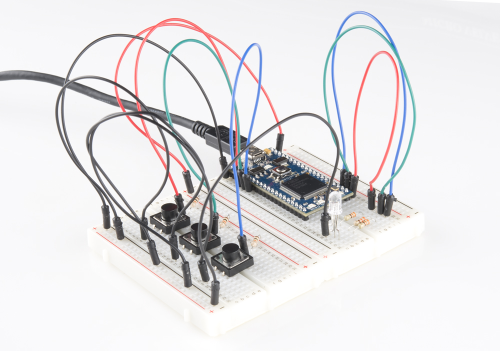
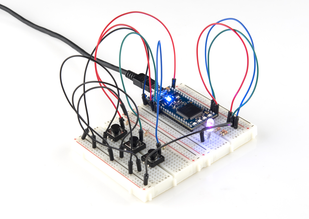
The Circuit
This circuit can be made with parts in the SparkFun mbed Starter Kit. Also, keep in mind that the LPC1768 box contains a USB mini-B cable for programming and power.
Parts List
To follow this experiment, you would will need the following materials if you did not order the SparkFun mbed starter kit. You may not need everything though depending on what you have. Add it to your cart, read through the guide, and adjust the cart as necessary. The experiment will be using 3x 330Ohm and 3x 10kOhm resistors.
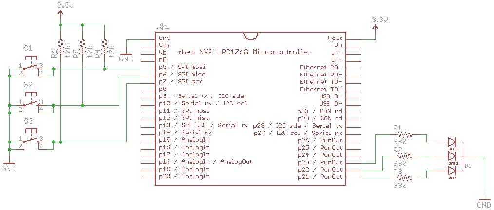
Schematic
Connections
Connect the LPC1768 to the buttons and LED in the following fashion.
| Polarized Components | Pay special attention to the component’s markings indicating how to place it on the breadboard. Polarized components can only be connected to a circuit in one direction. Polarized components are highlighted with a yellow warning triangle in the table below. |
Fritzing Diagram
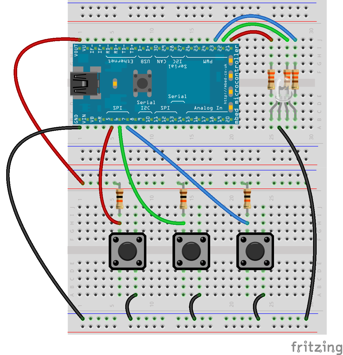
Note that the colors of the wires do not matter. Feel free to use any color you like! Do not worry if your kit does not have 5 black wires.
Hookup Table
Place the LPC1768 in the first breadboard with pin VOUT in position i1 and pin 20 in position b20.
Connect the rest of the components as follows:
| Component | Breadboard 1 | Breadboard 2 | ||||||
|---|---|---|---|---|---|---|---|---|
| RGB LED | b25 (RED) | b26 (GND) | b27 (GREEN) | b28 (BLUE) | ||||
| 330 Resistor | e25 | g25 | ||||||
| 330 Resistor | e27 | g27 | ||||||
| 330 Resistor | e28 | g28 | ||||||
| Pushbutton | d6 | d8 | g6 | g8 | ||||
| Pushbutton | d14 | d16 | g14 | g16 | ||||
| Pushbutton | d22 | d24 | g22 | g24 | ||||
| 10k Resistor | i6 | ( + ) | ||||||
| 10k Resistor | i14 | ( + ) | ||||||
| 10k Resistor | i22 | ( + ) | ||||||
| Jumper Wire | j1 | ( + ) | ||||||
| Jumper Wire | a1 | ( - ) | ||||||
| Jumper Wire | a5 | h6 | ||||||
| Jumper Wire | a6 | h14 | ||||||
| Jumper Wire | a7 | h22 | ||||||
| Jumper Wire | j20 | j25 | ||||||
| Jumper Wire | j19 | j27 | ||||||
| Jumper Wire | j18 | j28 | ||||||
| Jumper Wire | a26 | ( - ) | ||||||
| Jumper Wire | a8 | ( - ) | ||||||
| Jumper Wire | a16 | ( - ) | ||||||
| Jumper Wire | a24 | ( - ) | ||||||
Tips
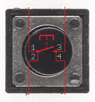
Pushbuttons
The leads across each other on the pushbuttons are always connected to each other. The leads on the same side are only connected when button is pressed.
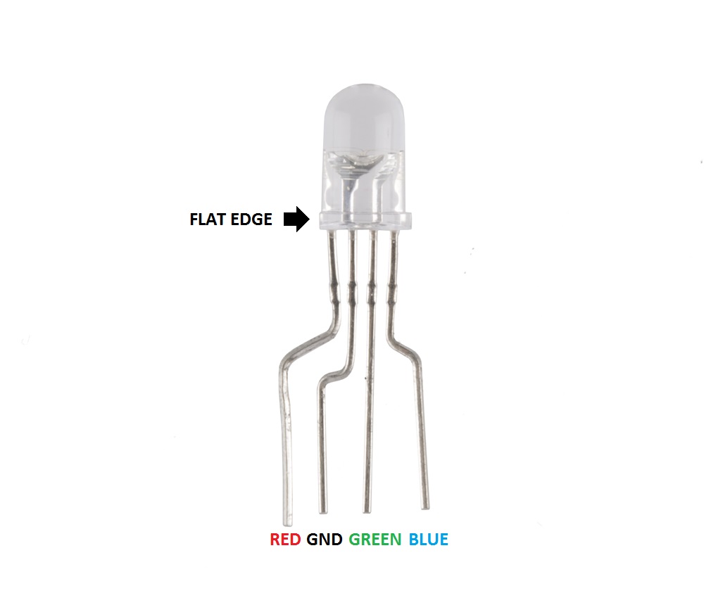
LED
You can use a set of needle nose pliers to bend the LED's leads and a pair of cutters to fit the LED in the breadboard. Note that there is a flat side on the plastic ring around the bottom of the LED. This denotes the side with the pin that controls the red color. See this tutorial to learn more about polarity.
Resistors
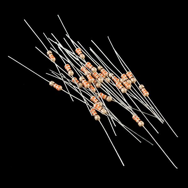
330 ohm resistors are given by the color code "orange orange brown."
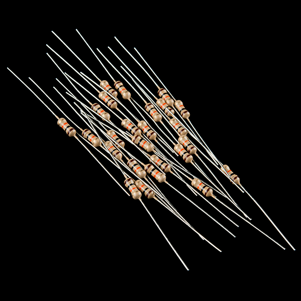
10k ohm resistors are given by the color code "brown black orange."
The Code
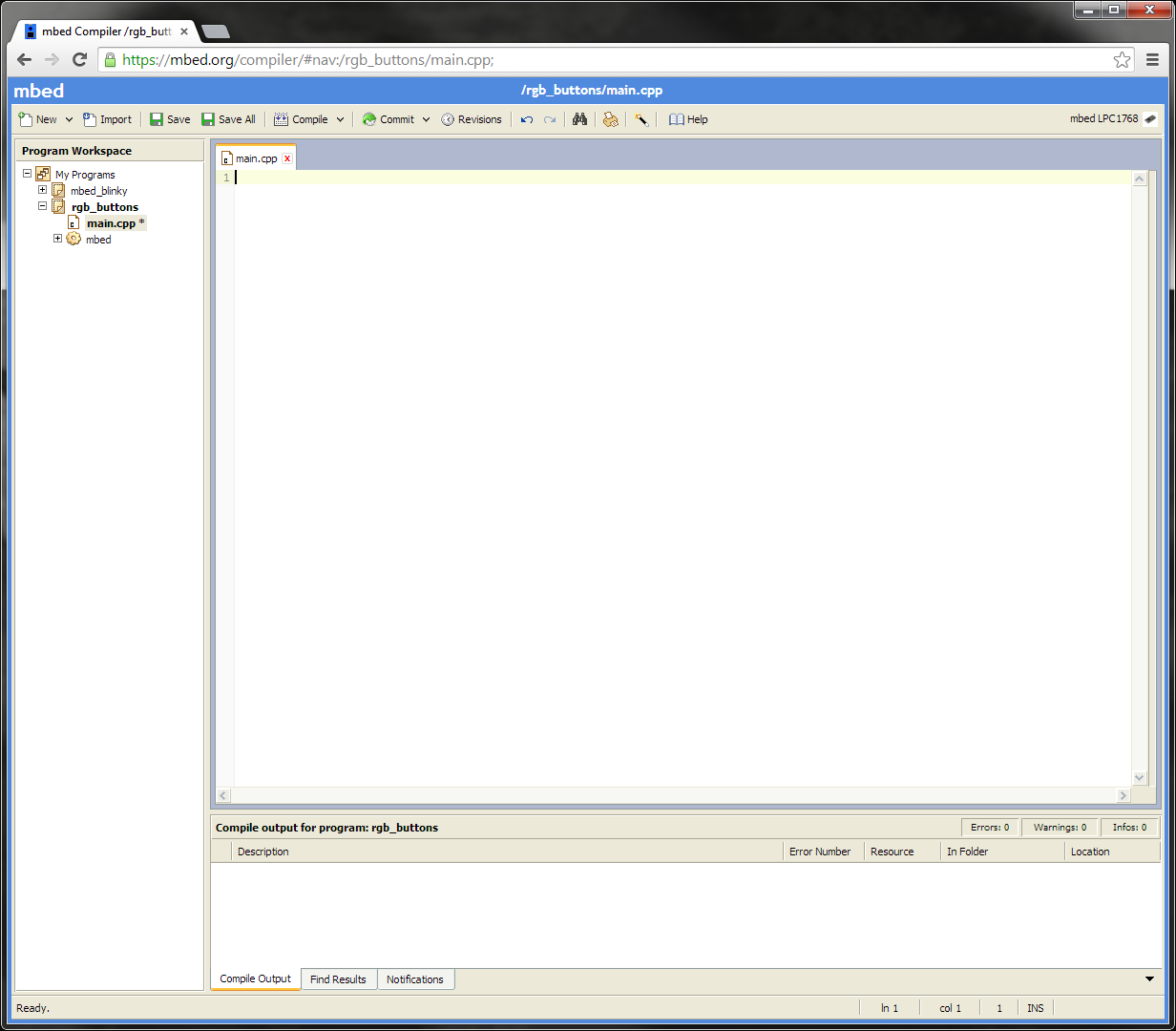
If you have not done so already, sign into your mbed.org account. Go to the Compiler and create a new program. Leave the template as "Blinky LED Hello World" and give it a name such as "rgb_buttons." Click OK and wait for your new program to be created.
Once that is done, click "main.cpp" under your project folder (e.g. "rgb_buttons") in the left "Program Workspace" pane. Delete all of the code in main.cpp so you are left with a blank project (we still want to use the "Blinky LED Hello World" template, as it automatically links "mbed.h" for us).
Program
Copy the following code into main.cpp of your rgb_buttons project.
language:c
#include "mbed.h"

// Define buttons
InterruptIn button_red(p5);
InterruptIn button_green(p6);
InterruptIn button_blue(p7);

// Define LED colors
PwmOut led_red(p21);
PwmOut led_green(p22);
PwmOut led_blue(p23);

// Interrupt Service Routine to increment the red color
void inc_red() {

    float pwm;

    // Read in current PWM value and increment it
    pwm = led_red.read();
    pwm += 0.1f;
    if (pwm > 1.0f) {
        pwm = 0.0f;
    }
    led_red.write(pwm);
}

// Interrupt Service Routine to increment the green color
void inc_green() {

    float pwm;

    // Read in current PWM value and increment it
    pwm = led_green.read();
    pwm += 0.1f;
    if (pwm > 1.0f) {
        pwm = 0.0f;
    }
    led_green.write(pwm);
}

// Interrupt Service Routine to increment the blue color
void inc_blue() {

    float pwm;

    // Read in current PWM value and increment it
    pwm = led_blue.read();
    pwm += 0.1f;
    if (pwm > 1.0f) {
        pwm = 0.0f;
    }
    led_blue.write(pwm);
}

// Main loop
int main() {

    // Initialize all LED colors as off
    led_red.write(0.0f);
    led_green.write(0.0f);
    led_blue.write(0.0f);

    // Define three interrupts - one for each color
    button_red.fall(&inc_red);
    button_green.fall(&inc_green);
    button_blue.fall(&inc_blue);

    // Do nothing! We wait for an interrupt to happen
    while(1) {
    }
}
Run
Click the "Compile" button to download a binary file with your compiled program. Copy that file to the LPC1768. You can choose to delete the previous mbed_blinky_LPC1768.bin or just leave it there. If you have more than one .bin file on the mbed when you press the restart button, the mbed will choose the newest file to load and run.
Press the LPC1768's restart button. You should be able to press any of the 3 buttons on your breadboard to increment the red, green, and blue intensity of the LED. Note that when you reach the maximum brightness, the intensity resets to 0.
Concepts
What is going on in our program? We should understand a few concepts about our seemingly simple RGB LED and button program that are crucial in embedded systems.
Pull-up Resistors
We use 10kΩ pull-up resistors to prevent shorting 3.3V to ground whenever we push one of the buttons. Additionally, the pull-up resistors on the microcontroller (LPC1768) pin holds the pin at 3.3V by default until the button is pushed. Once pushed, the line is pulled down to ground, so the pin goes from 3.3V to ground. We can use that falling edge (3.3V to 0V) to trigger an interrupt within the microcontroller. To learn more about pull-up resistors, see our tutorial here.
Functions
If you are not familiar with C syntax, you might want to brush up on some of the basics.
In the above code, we created 3 functions: inc_red(), inc_green(), inc_blue(). Functions generally perform some action when called, and replace the much-maligned GOTO statement. They also allow us to re-use code without having to copy-and-paste sections of code over and over again.
Each time we call one of the functions (e.g. inc_green()), the lines of code within that function are called, and then the function exits, returning program execution to just after the function call.
Notice that we placed the three functions above main(). When the compiler looks at the code, it needs to have functions declared before they are used in the code (within main() in this case).
If you put main() before the functions, you would get a compiler error. That's because the compiler does not know what int_red(), etc. are when it sees them in main(). Try it!
Objects
We are using C++ to write all of our programs. If you have never used C++ before, the syntax might appear a bit foreign. We recommend reading about some basic C++ syntax first.
In the program, we create objects for each of our buttons and LEDs. For example:
language:c
InterruptIn button_red(p5);
and
language:c
PwmOut led_red(p21);
button_red is an instance of class InterruptIn. Think of a class as a "blueprint" that lets us create any number of instances (i.e. objects). Each instance is tied to a variable (e.g. button_red). In this case, button_red is an InterruptIn object.
Objects have special properties that let us call functions within that object (called "member functions") and manipulate data stored in the object (data in objects is stored as "data members"). For example, we create a PwmOut object named led_red. Later in the code, we call the member function led_red.write(0.0f), which tells the led_red object to perform some action (change the PWM of the associated pin in this case - see PWM below!).
We pass in the parameter p5 (a special variable known to the mbed compiler - it points to the location of pin 5 in software) when we create an InterruptIn object. This tells the mbed which pin to bind the interrupt to.
Now that we have created an InterruptIn object, we can call member fucntions within that object. The InterruptIn class defines a fall() member function, which allows us to set a function to be called whenever a HIGH-to-LOW transition occurs on the pin (pin 5 in this case).
language:c
button_red.fall(&inc_red);
Note that the '&' symbol is used to indicate the address of the inc_red function.
Interrupts
Interrupts are an integral part of embedded systems and microcontrollers. Most programs that you might be used to run sequentially, meaning that the program executes each line in order (and jumps or loops where necessary). In contrast, many microcontrollers rely on subroutines known as "Interrupt Service Routines" to handle external and internal events.
In our mbed program, we "attach" an interrupt to our button pins and tie this interrupt to a function call (e.g. inc_red()). The line
button_red.fall(&inc_red);
says that whenever we see a falling digital signal (i.e. from 3.3V to 0V), we must stop whatever we were doing and execute the function inc_red(). This is similar to callbacks often found in programming but can be tied to external (i.e. outside the microcontroller) events.
YouTube user Patrick Hood-Daniel offers a great explanation of interrupts and some example code in a different microcontroller (Atmel AVR ATmega32):
PWM
To control the brightness of the LEDs, we do not vary the current going into the LED. Rather, we rapidly turn the LED off and on to give the appearance of a dimmer LED. This is known as "Pulse-Width Modulation" (PWM). Note that we are flipping the LED off and on so fast that generally our eyes cannot see the flickering.
We adjust the "duty cycle" of this flipping process in order to control the brightness. Duty cycle just refers to how long our LED stays on in relation to how long it stays off.

The higher the duty cycle (e.g. 75% in the image above), the brighter the LED will appear to be. At lower duty cycles (e.g. 25%) the LED will hardly appear to be on. For a full tutorial on PWM, see Pulse-width Modulation.
In our rgb_buttons program, we use mbed's built-in PwmOut object to control PWM on several of the LPC1768 pins. We can read the PWM value with the .read() method and set a new PWM value with .write(). We use a floating point number to specify the duty cycle. This can be between 0.0 (0% duty cycle) to 1.0 (100% duty cycle).
Going Further
We've covered three important concepts in this tutorial: user input with buttons (using pull-up resistors), interrupts, and PWM. If these topics provide some confusion, feel free to read through the "Digging Deeper" section to learn more about these topics in greater detail.
Beyond the Tutorial
- See how the LED changes when you press a button down? Can you make it so that the LED changes when you release a button?
- Since we are using interrupts, our while(1){} loop is empty. Make something happen while waiting for a button push! For example, flash another LED in that while loop.
- Can you re-create the functionality of the program without using any interrupts?
- You might notice that the LED changes accidentally sometimes when you release a button. This is caused by a phenomenon known as contact bounce. Can you create a way to remove contact bounce (known as "debouncing")? This can be done in hardware or software.
Digging Deeper
- If you are not familiar with C++, you may want to read up on Object Oriented Programming
- It might also be a good idea to brush up on C syntax and C++ syntax
- Read about pull-up resistors
- Read about embedded interrupts and about mbed's interrupt handling
- Read about pulse-width modulation and about how mbed built-in PWM features