micro:arcade Kit Experiment Guide
 D___Run___,
  bboyho
 Experiment 3: Fun with the Joystick
Introduction
So far we have been building and programming games that either don't have a score or require you to keep track. It is now time to pass that job off to the micro:bit. You are now going to build a simple collection game where "coins" are falling down the screen and you will control your sprite with the joystick to collect them. You will also only have 10 second before the game ends. At the end of the 10 seconds the game will be over and your score will be displayed.
Parts Needed
- 1x micro:bit Board (Not Included with Kit)
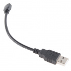
- 1x Micro-B USB Cable (Not Included with Kit)
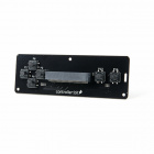
- 1x controller:bit Carrier Board
- 1x Arcade Joystick
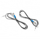
- 4x Spade Wire Connectors
Didn't get the kit? Have no fear! Here are the parts you will need to complete this experiment. You may not need everything though depending on what you have. Add it to your cart, read through the guide, and adjust the cart as necessary.
Suggested Tools
- Ball point pen
- Hobby knife or scissors
- 12" ruler
Suggested Reading
- Getting Started with the micro:bit - Basic hookup and programming of the micro:bit
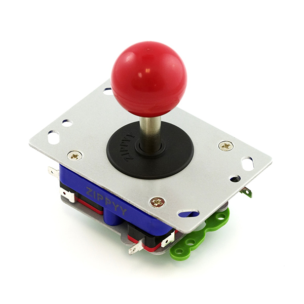
Meet the Joystick
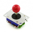
The arcade joystick is the heavy duty short handled joystick that we are all familiar with from our favorite game cabinet of our childhoods (or for most of us... yesterday).
This joystick operates as four momentary push switch, one for each direction. Each switch is opposite from the directions that it controls. For example is you press the joystick "UP" the switch on the "DOWN" side of the joystick is pressed, so you have to wire it backwards to the direction the joystick is pressed.
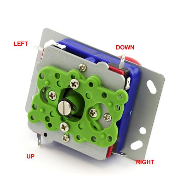
The wiring for this experiment will use the common (COM) and the Normally Open (NO) terminals on the switches.
Hardware Hookup
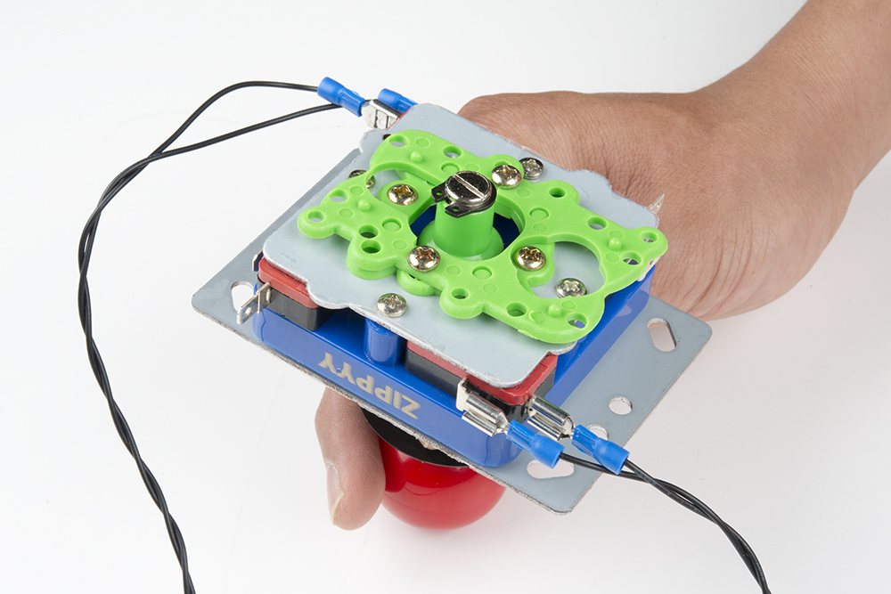
The hardware hookup should be pretty familiar to you in a way. The Arcade joystick uses the same type of switches as the arcade buttons with the same spade connects. Hookup a spade connector wire to each switches COM and NO terminals as shown below. For this specific game you will only need the two switches that control left and right movement.
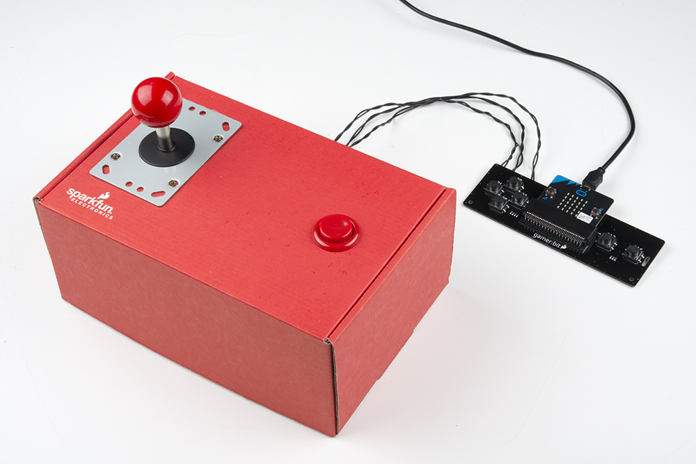
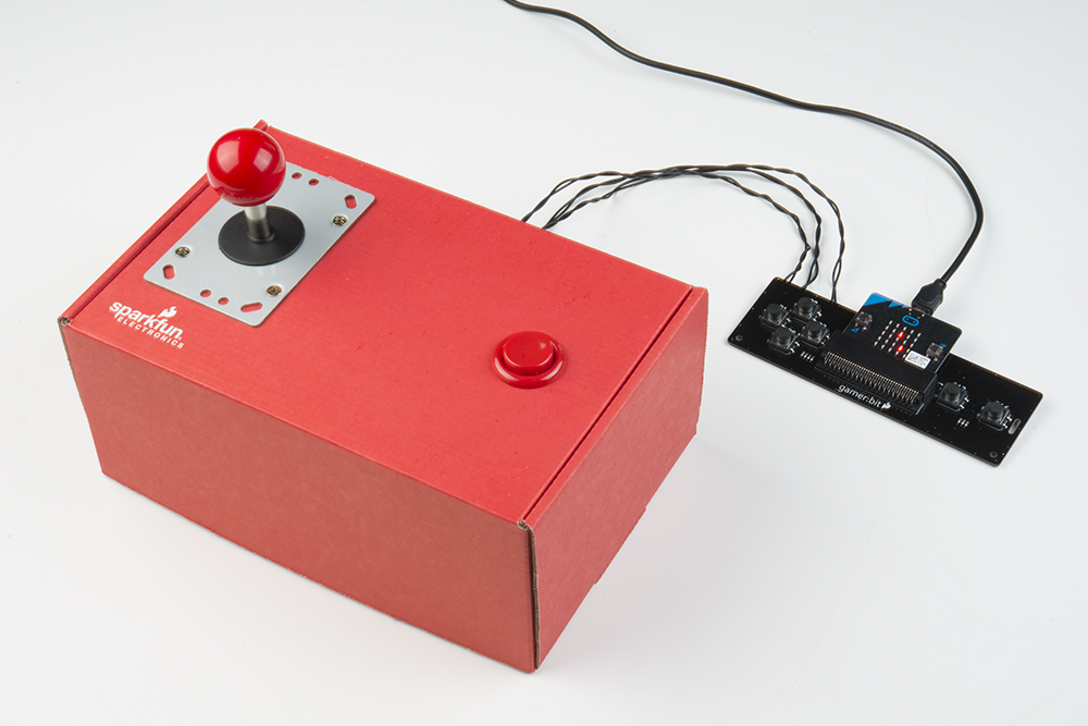
When using the joystick or the arcade buttons, it is always a great idea to mount them to a piece of cardboard or in shoe box (the box the kit comes in is the perfect size). You can mount the joystick by cutting out mounting holes for the joystick's frame.
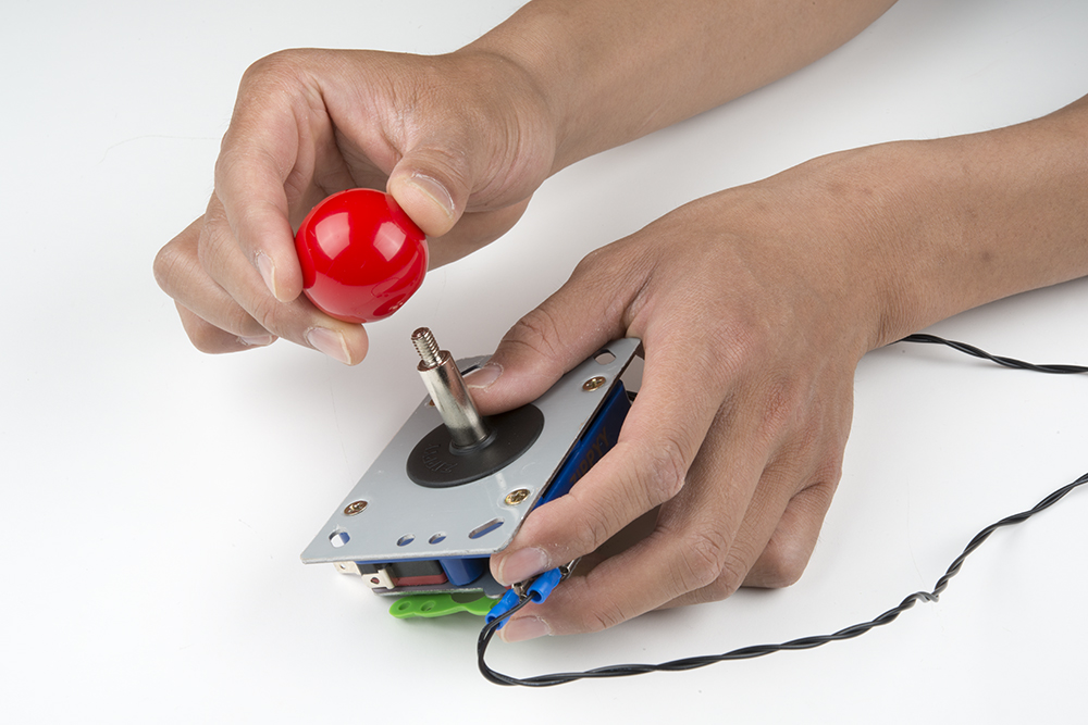
To begin, remove the knob of the joystick by unscrewing it from the shaft. This also allows you to remove the black cover ring of the joystick as well.
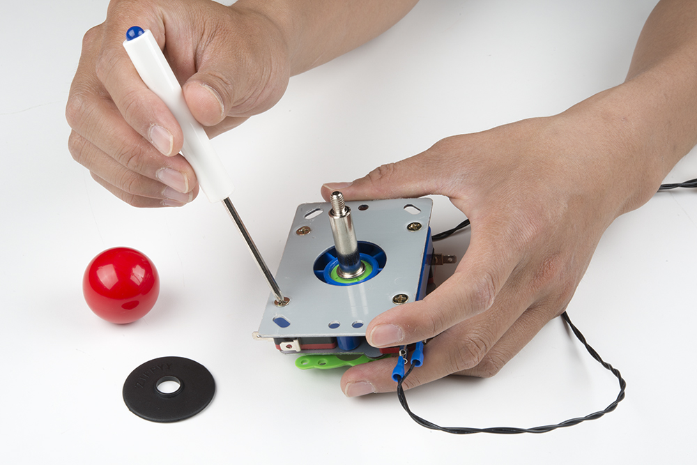
Using a Phillips head, we can remove the four screws that are holding down the frame. The SparkFun mini screwdriver was used in this experiment to remove the screws.
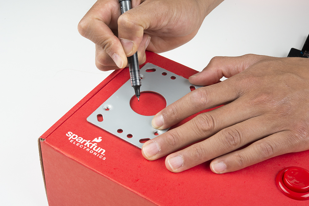
Once the frame has been removed, we can use it to draw the mounting holes. Place the other parts in a safe location as while cutting the cardboard box.

On the top left hand side of the box, draw the four mounting holes for the screws. Additionally, draw a hole for the shaft. Ensure that there is enough room in the enclosure to slide the spade connector into the microswitch's terminal. This would apply to the microswitch's close to the sides of the enclosure.
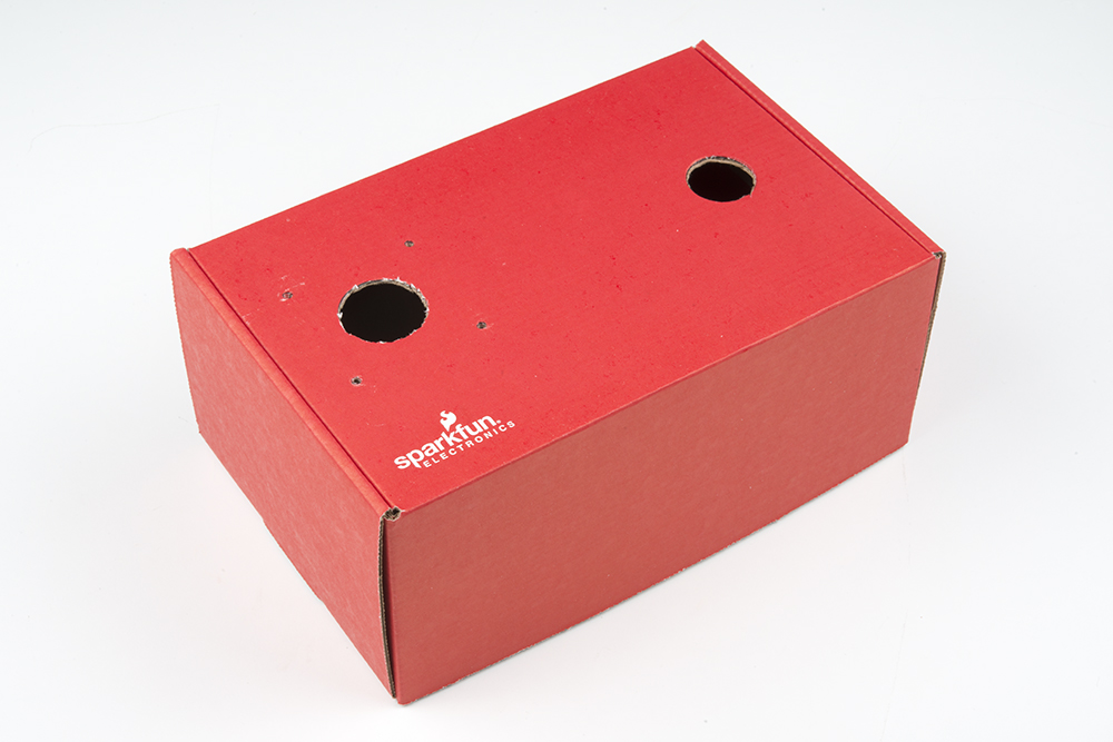
Using the mini screwdriver, carefully poke holes through the four mounting holes. A craft knife or pair of scissors can be used cut the hole for the shaft.
Now that the mounting holes are cut, we can attach the joystick to the cardboard box. Hold the frame against the top of the cardboard box. Attach one screw through the mounting hole using one hand. Next, pass the shaft of the joystick up through the bottom of the box until one mounting hole lines up with the screw. Twist the screw in with your hand just enough to sandwich the cardboard between the joystick and the frame. Continue adding the rest of the screws to the joystick and tighten up the scerws using the mini screwdriver.
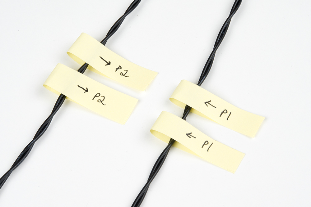
A great idea to be able to keep things straight is to label each pair of wires at the stripped ends so that when you hook it up to your controller:bit carrier board, you don't have to constantly tracing the wires back to the correct switch.
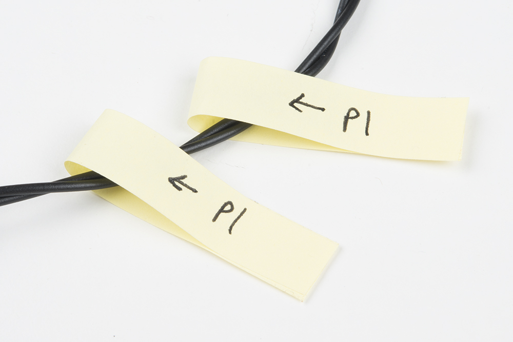
Using some sticky notes, label each wire twice for the poke-home connectors labeled P1 and P2. You can slide one label close to the joystick and the other for the controller:bit.
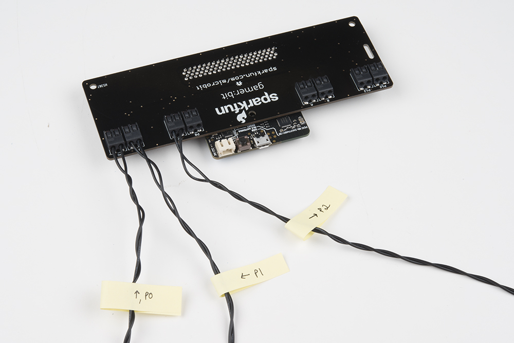
Hookup the stripped ends into the poke-home connectors as explained in the previous experiment by pressing down on the connector tab with a ballpoint pen, inserting the bare end of the wire into the connector, and releasing the tab. The connector will hold tight onto the wire with a snug connection. While we are at it, feel free to reconnect the concave button and label those wires.
Finally, you can return the black cover ring and knob to the top of the joystick. The concave button was not used in this experiment but feel free to reattach it back to the box.

Give a quick test to make sure everything works... you should feel a nice click from the switches inside the box.
Running Your Script
You can either download the following example script below and drag and drop it onto your micro:bit, or use it as an example and build it from scratch in MakeCode.
Code to Note
Let’s take a look at the code blocks in this experiment.
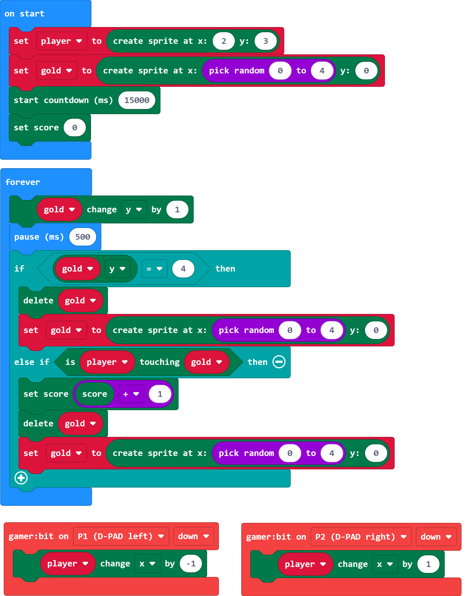
Create Sprite
As in the previous experiments we use the Create Sprite block. This time though we use it multiple times in the program. We create our player sprite, but also a sprite for the "gold coins" that are falling that you want to capture before they go by.
Start Countdown (ms)
The start countdown block starts a timer for the length of milliseconds. At the end of that countdown, it runs a game over animation and displays the score. This simplifies this program a lot. We would have had to program that all by ourselves.
Set Score
To make sure that you are starting with a fresh game we set the score to 0 by using the Set Score block in On Start and pass it the number 0.
Change Y by
In the forever loop, we change the y value of the gold spite by 1. This creates a falling animation after the "gold" has been created in a random place along the top of the LED array.
Touching
As the "gold" falls down, we check if the "gold" sprite is touching the "player" sprite. If it is, then the player scores and the following happens.
- The player scores a point.
- The "gold" sprite is destroyed.
- A new "gold" sprite is created at the top of the LED array.
If the player misses the "gold" then it passes by the player. If the Y coordinate of the "gold" is equal to 4, then it is destroyed and and a new one is created without the player gaining a point.
Score + 1
To add to a players score, we use the set score block again, but this time in a different way. We set the score to the score variable plus 1.If you wanted to hack this project and have this subtract a point, you would change the math block from addition to subtraction.
Delete
To remove a sprite from the screen, you use the delete block that will destroy the variable storing the sprite and its information.
What You Should See
When the game starts, your sprite will show up one row above the bottom of the LED array. You control your sprite with the joystick to move left and right. "Gold" will start to fall from the top of the screen and you need to move to catch it. This will go on for 15 seconds. At the end of the 15 seconds, the game will end with the "game over" sequence and display your score. Wahoo, let's play again.
Troubleshooting
The direction of the joystick is opposite - It gets us all the time! Flip the wires around to the opposite side of the joystick from where they are are. Or, change the wires at the controller:bit.
Nothing reacts! - Double check that your controller:bit events are monitoring the correct pins that your joystick is wired to!
I can't unhook the poke-home connector - Make sure you are using a ball point pen and pressing down on the tab. Don't just pull on the wire!