micro:bit Educator Lab Pack Experiment Guide
Introduction
Huzzah! You have the micro:bit educator lab pack! Now what? Well, look no further; we have some experiments laid out here that are not only a great introduction to the micro:bit, but will prepare you for the wild world of micro:bit expansion.
The micro:bit is an incredibly versatile little board that makes it a great introduction to electronics and beyond. It is packed full of lovely little features, including LEDs, temperature sensor, accelerometer, bluetooth/radio... the list goes on. If you've never used the micro:bit before, Getting Started with the micro:bit is a great place to start. It will introduce you to the online development environment and give you a run down of all the extras and where they live on the board.
Getting Started with the micro:bit
September 2, 2021
Suggested Reading
If you are entirely new to the world of electronics, we recommend you start with some of the following concepts and tutorials:
PCB Basics
What is a Circuit?
Voltage, Current, Resistance, and Ohm's Law
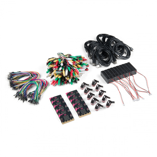
Included Materials
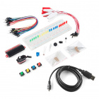
The micro:bit educator lab pack includes the following:
- 10x micro:bit — The brains of the outfit with a bunch of on-board components. The version will vary depending on the lab pack that you ordered.
- 10x USB micro-B Cable — This 6-foot cable provides you with a USB-A connector at the host end and standard B connector at the device end.
- 10x 2xAAA Battery Pack — AAA battery pack with the JST connector that fits the micro:bit.
- 10x Jumper Wires Standard 7in M/M (30pk) — These are high-quality wires that allow you to make connections with components on the breadboard.
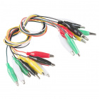
- 10x Alligator Test Leads (10 pk) — A great way to connect individual components to the micro:bit ring connectors.
- 10x Small Servo — Here is a simple, low-cost, high-quality servo for all your mechatronic needs.
- 10x Mini Speaker — BUZZZZ! Used to make different frequencies of sound. (not included in LAB-17361)
| micro:bit educator lab pack SKU | Revision History |
|---|---|
| LAB-17361 | - Switched to micro:bit V2. - Remove mini speakers since micro:bit V2 includes a built-in speaker. |
| LAB-15230 | Switch to 2xAAA battery holder with a built-in switch. |
| LAB-14302 | Initial release. |
Hello World!
"Hello World" is the term we use to define that first program you write in a programming language or on a new piece of hardware. Essentially, it is a simple piece of code that gives you a quick win (fingers crossed) and a first step in learning. It also gives you a chance to make sure everything is up and running and A-OK.
For your first "Hello World" we are going to create a simple animation on the LED array that repeats forever. If you just want the complete program, you can see it here. To see a step-by-step explanation of how we built the program, continue reading!
Building 'Hello World'
A "Hello World" on the micro:bit is a little different than on a normal run-of-the-mill microcontroller. The micro:bit has no single LED to blink on its own, as you would find on the Arduino or similar boards. What the micro:bit does have is an LED array! So, the "Hello World" for the micro:bit is to draw something using the LED array!
When you open MakeCode you are greeted with two blocks: the On Start block and the forever block. The On Start block is all of your code that will execute at the very beginning of your program and only run once. The forever block is code that will loop over and over again...forever.
We are going to use the forever block for building this "Hello World." We now need to start adding blocks to forever.
First, click on the Basics category. These blocks are, well, the basic building blocks of a BuildCode program. It will expand into a number of options. Click and drag the show leds block over and place it inside of your forever block. Notice that the block is keyed to fit inside of the forever block, and if you have the volume up on your computer you will hear a satisfying 'click' noise when you let go of the block.
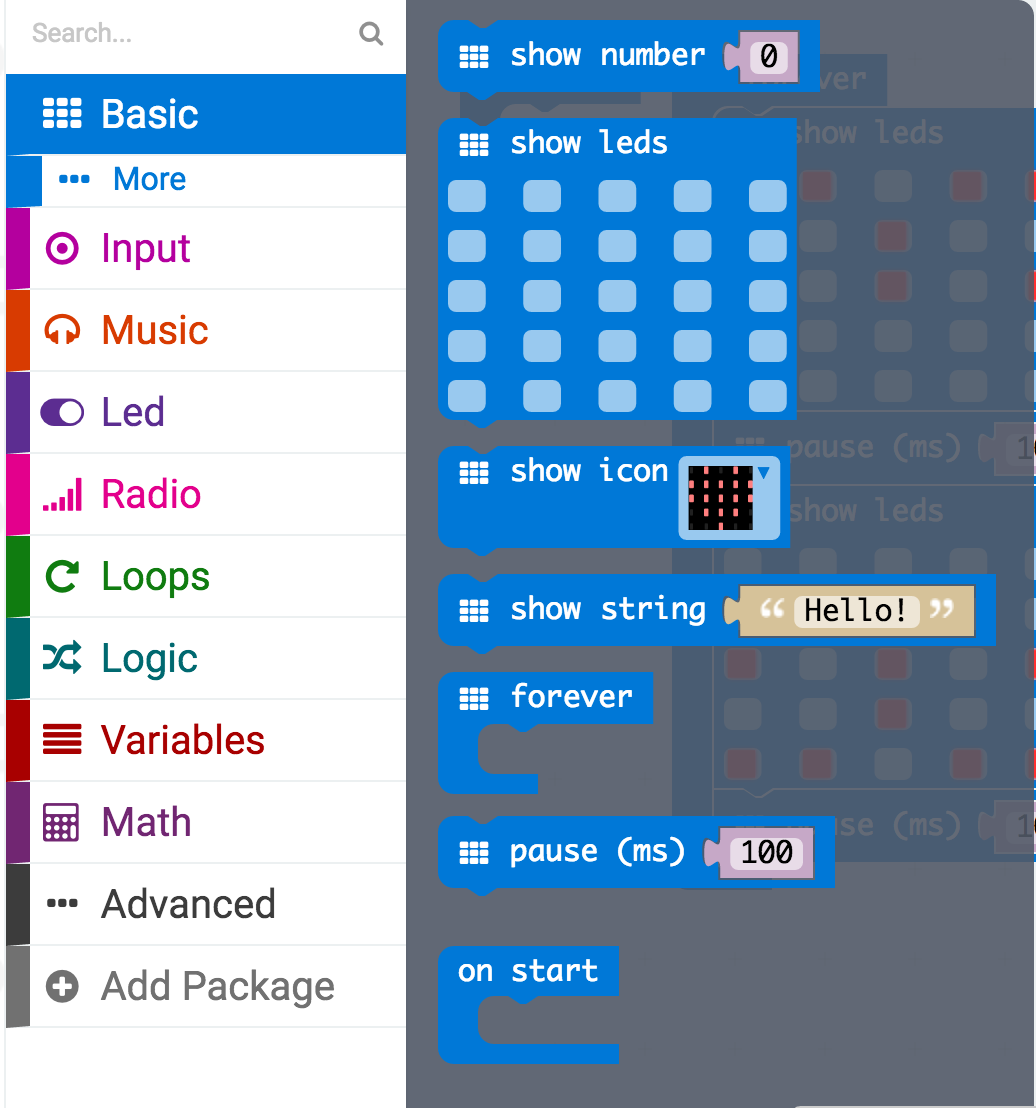
The show leds block has an array of squares that symbolize the LED array. If you click on a square, it will turn red, which means that it is on. Draw a simple pixel art shape by turning different LEDs on or off; you should be able to see the outcome in your simulator on the lefthand side of your window.
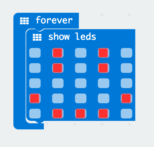
To turn this static image into an animation, we need another show leds block to place just under the first block. You can then make a second drawing with this set of rectangles. In your simulator you will see the images switching really, really fast. We need to slow this down!
To slow your animation down, you will use the pause block, which is under the basic block set. The pause block is just what it says; it tells the micro:bit to pause and wait for a certain amount of time. Place two pause blocks in the program as shown.
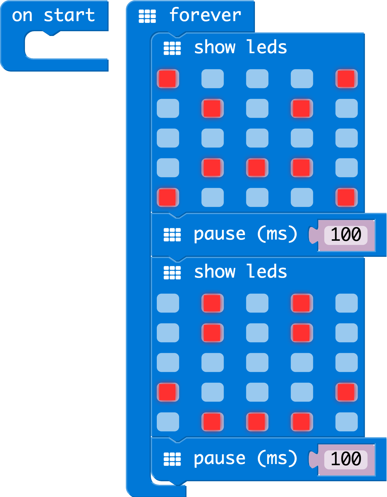
The reason we are using two and placing one at the end is that this program is a loop. Without the block at the end, the image in your animation will change really, really fast.
We have built up an example in the next section where you can download the file and try it out on your own micro:bit, or use the simulator. If you want to play around with the code and make some changes, go ahead and click the Edit button in the widget, and it will open a MakeCode editor for you to start hacking "Hello World." Enjoy!
Download Your Program
Either copy and paste, or recreate the following code in your own MakeCode editor. You can also just download this example by clicking the download button in the upper righthand corner of the code window.

This will download your program file to your standard download location, probably the Downloads folder on your computer, or whatever location you have set in your download preference.
You then simply click and drag your program file from its download location to your micro:bit drive, which shows up as an external device.
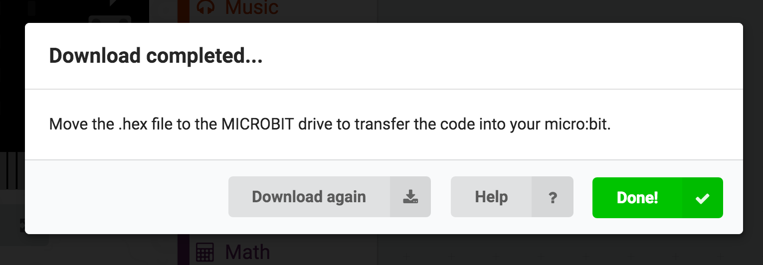
That's it!
Your micro:bit will flash for a few seconds, and then your program will start automatically. Yes! Win!
Experiment 1: Reading the Temperature Sensor
Introduction
A temperature sensor is exactly what it sounds like --- a sensor used to measure ambient temperature. The micro:bit has a temperature sensor sneakily built into it's processor chip. In this experiment we'll read that sensor and set up the micro:bit to display the ambient air temperature in both Celsius and Fahrenheit!
Parts Needed
You will need the following parts:
- 1x micro:bit
- 1x Micro-b USB Cable

Run Your Script
Either copy and paste, or re-create the following code into your own MakeCode editor by clicking the open icon in the upper right-hand corner of the editor window. You can also just download this example by clicking the download button in the lower right-hand corner of the code window.
Code to Note
Let's take a look at the code blocks in this experiment.
](https://cdn.sparkfun.com/assets/learn_tutorials/4/9/9/MicroBitLabPackTemperatureCode.png)
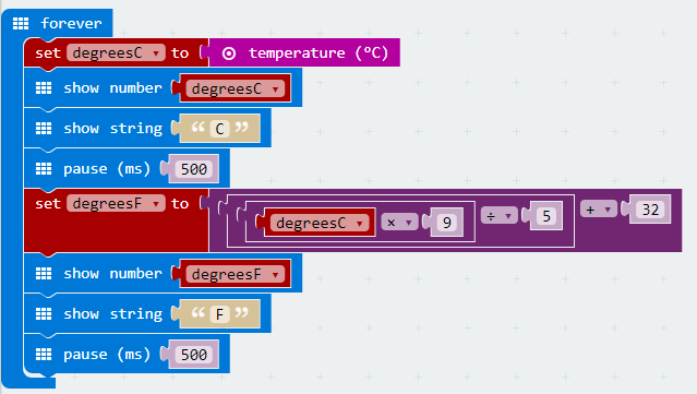
Set degreesC
Since the microcontroller also doubles as a temperature sensor, temperature is a built in value. In the Variables section of the makecode IDE, you can choose to create a new variable based on that temperature value.
Show Number
The Show Number block accepts a number value (or variable) and then displays it on the LED array.
Show String
The Show String block scrolls the string across the LED array after your temperature value.
Setting and Calculating degreesF
The Fahrenheit temperature can be calculated using blocks from the Math section. To convert C to F, the equation is F = C x 9/5 + 32. You can then display the Fahrenheit temperature using the same blocks you used to display the Celsius temperature.
What You Should See
When your micro:bit turns on, the temperature reading in Celsius will be displayed and scrolled across the LED array followed by the temperature reading in Fahrenheit.
Troubleshooting
Temperature Value is Unchanging
Try pinching the sensor with your fingers to heat it up or pressing a bag of ice against it to cool it down.
Temperature Value is Unchanging
Try holding the sensor near a heater (NOT TOO CLOSE!!) to heat it up or press a bag of ice against it to cool it down.
Experiment 2: Using a Servo Motor
Introduction
This experiment is your introduction to the servo motor, which is a motor that you can tell to rotate to a specific angular location. You will program it to rotate to a series of locations, then sweep across its full range of motion, and then repeat.
Parts Needed
You will need the following parts:
- 1x micro:bit
- 1x micro-B USB Cable
- 3x Alligator Leads
- 3x M/M Jumper Wires
- 1x Servo


Suggested Reading
Before continuing with this experiment, we recommend you be familiar with the concepts in the following tutorial:
Hobby Servo Tutorial
May 26, 2016
Introducing the Servo Motor
Unlike the action of most motors that continuously rotate, a servo motor can rotate to and hold a specific angle until it is told to rotate to a different angle. You can control the angle of the servo by sending it a PWM (Pulse Width Modulation) pulse train; the PWM signal is mapped to a specific angle from 0 to 180 degrees.

Inside of the servo there is a gearbox connected to a motor that drives the shaft. There is also a potentiometer that gives feedback on the rotational position of the servo, which is then compared to the incoming PWM signal. The servo adjusts accordingly to match the two signals.
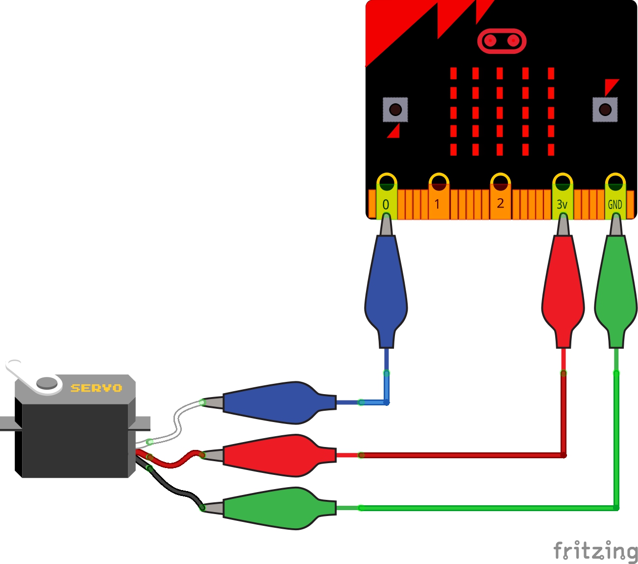
In this experiment, the servo is powered through 3.3 volts on the red wire and ground on the black wire; the white wire is connected to pin P0.
Hardware Hookup
Ready to start hooking everything up? Check out the wiring diagram below to see how everything is connected.
| Polarized Components | Pay attention to the servo's wire colorings and how they connect to the micro:bit. Polarized components can only be connected to a circuit in one direction. |
Wiring Diagram for the Experiment
Run Your Script
Either copy and paste, or re-create the following code into your own MakeCode editor by clicking the open icon in the upper right-hand corner of the editor window. You can also just download this example by clicking the download button in the lower right-hand corner of the code window.
Code to Note
Let's take a look at the code blocks in this experiment.
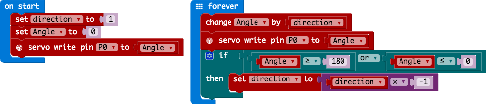
Set "Direction To"
In the On Start block we set the direction variable to 1. This value will be toggled between 1 and -1 to determine the direction we want the servo to sweep.
Servo Write
We use the Servo Write block to control a servo connected to a specific pin to rotate to a specific angle we pass it in degrees. We use a variable we have labeled as degrees. You can use this command to just write any angle between 0 and 180 to a servo motor at any time, but do remember to add a small pause to make sure that you give it enough time to respond before moving to the next angle.
Change by
If you want to increment or decrement a given variable by a certain value, which is positive or negative, you use the Change by block. You can select the variable you want to change and then the value you want to increment by (positive value) or decrement by (negative value). We increment the angle by 1 degree using this block.
Set "Direction to Direction x -1"
To change the direction of the servo once it reaches 0 or 180, we do some fancy math to multiply the direction variable by -1 to toggle it from a positive value to a negative number or a negative number to a positive value. That way when we use the change by block, the number is positive or negative.
What You Should See
When powered up you should see the servo move to a single location (0 degrees) and then start to sweep to 180 degrees back and forth until you turn it off or tell it to go to a different angle.

Troubleshooting
Servo Not Twisting
Even with colored wires, it is still shockingly easy to plug a servo in backward. This might be the case.
Still Not Working
A mistake we made a time or two was simply forgetting to connect the power (red and black wires) to 3.3 volts and ground (GND).
Experiment 3: Using a Buzzer
Introduction
In this experiment, we will again bridge the gap between the digital world and the analog world. We'll be using a piezo buzzer that makes a small "click" when you apply voltage to it (try it!). By itself that isn't terribly exciting, but if you turn the voltage on and off hundreds of times a second, the piezo buzzer will produce a tone. And if you string a bunch of tones together, you've got music! This circuit and set of code blocks will create a simple sound machine.
Parts Needed
You will need the following parts:
- 1x micro:bit
- 1x micro-B USB Cable
- 2x Alligator Leads
- 1x Piezo Buzzer
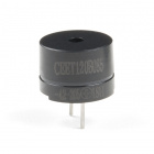
Introducing the Piezo Buzzer
The buzzer is a small component with a piece of metal in it that moves when you apply a voltage across it. This motion causes a small sound, or "click."

If you turn the voltage on and off fast enough, you get different beeps, squeals, chirps and buzzes. You can use PWM to control the speed of turning the piezo on and off --- and, in turn, the audio frequency coming out of the buzzer. Adjusting the PWM enables you to get legitimate notes out of the buzzer.
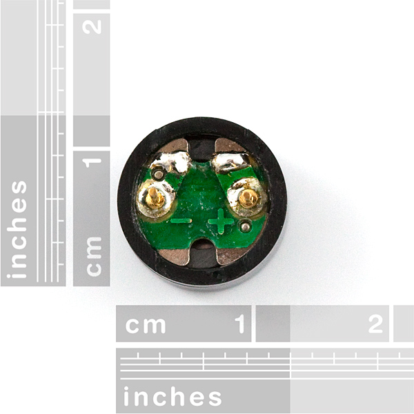
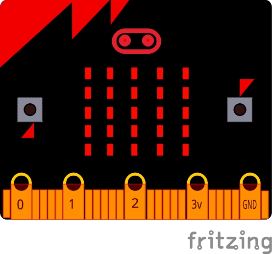
If you received one in the previous lab pack, you can flip the buzzer over and look at the bottom. You will see that one pin has a (+) next to it. That pin gets connected to a signal from the P0 pin. The other pin should be connected to ground.
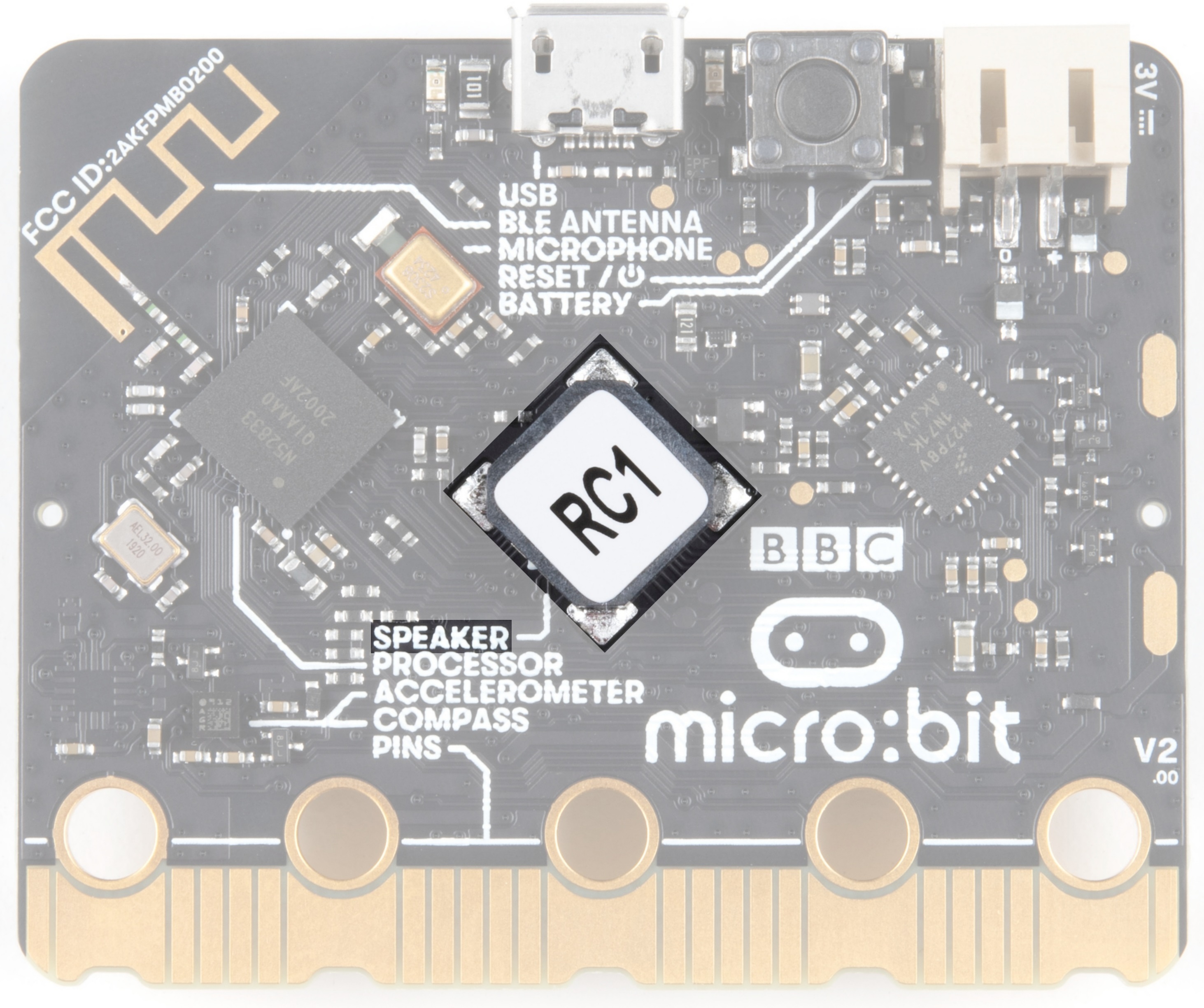
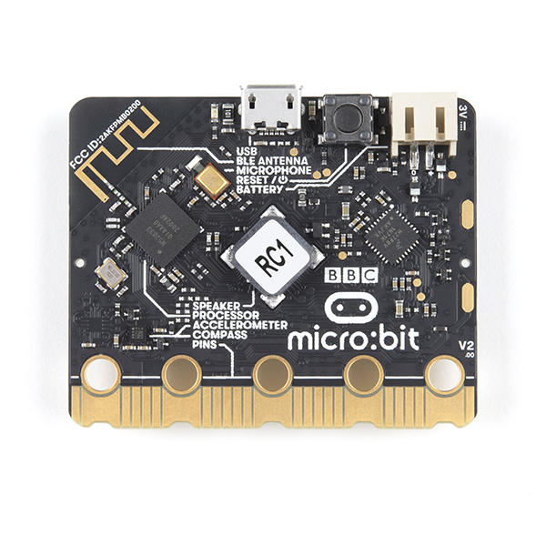
For users with micro:bit v2, there is a built-in piezo buzzer on the back of the board. If the sticker is removed, you will notice a polarity sign (e.g. "+") on the component as well.
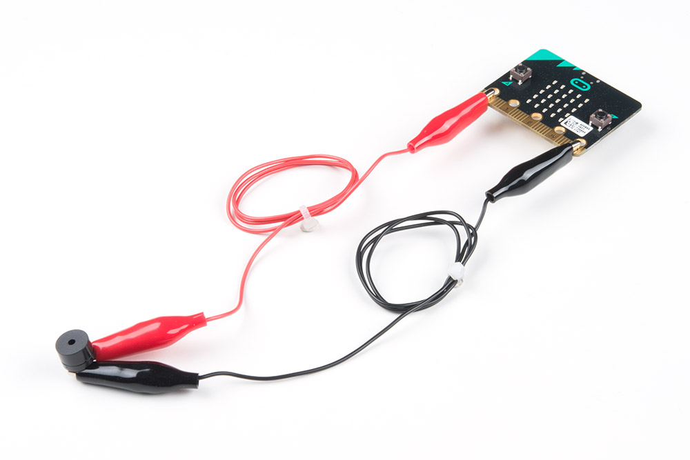
Hardware Hookup
Ready to start hooking everything up? Check out the wiring diagram below to see how everything is connected.
| Polarized Components | Pay special attention to the component’s markings indicating how to connect it to the micro:bit. Polarized components can only be connected to a circuit in one direction. |
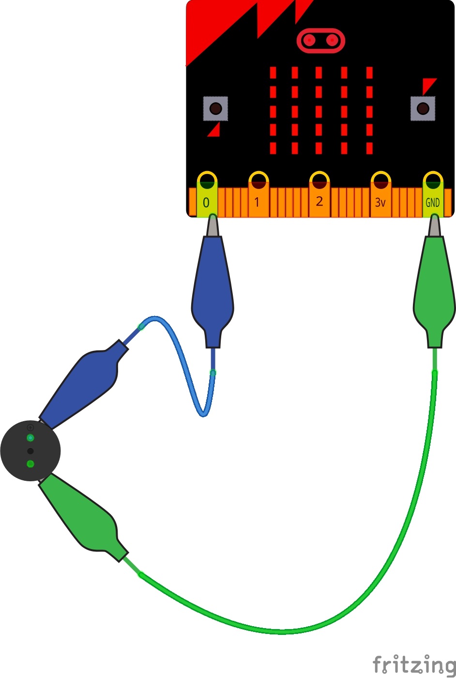
Wiring Diagram for the Experiment
For users wiring an external piezo buzzer with micro:bit V1, you would follow the diagram below.
For users with the micro:bit V2, you do not need to connect anything for this example since it has a built-in piezo buzzer! You will just need to define the output in code.
Run Your Script
Either copy and paste, or re-create the following code into your own MakeCode editor by clicking the open icon in the upper right-hand corner of the editor window. You can also just download this example by clicking the download button in the lower right-hand corner of the code window.
For users with micro:bit V1, simply remove the
set built-in speaker code block before compiling and downloading the program in the editor. Of course, you can head back to the old code as well. Code to Note
Let's take a look at the code blocks in this experiment.
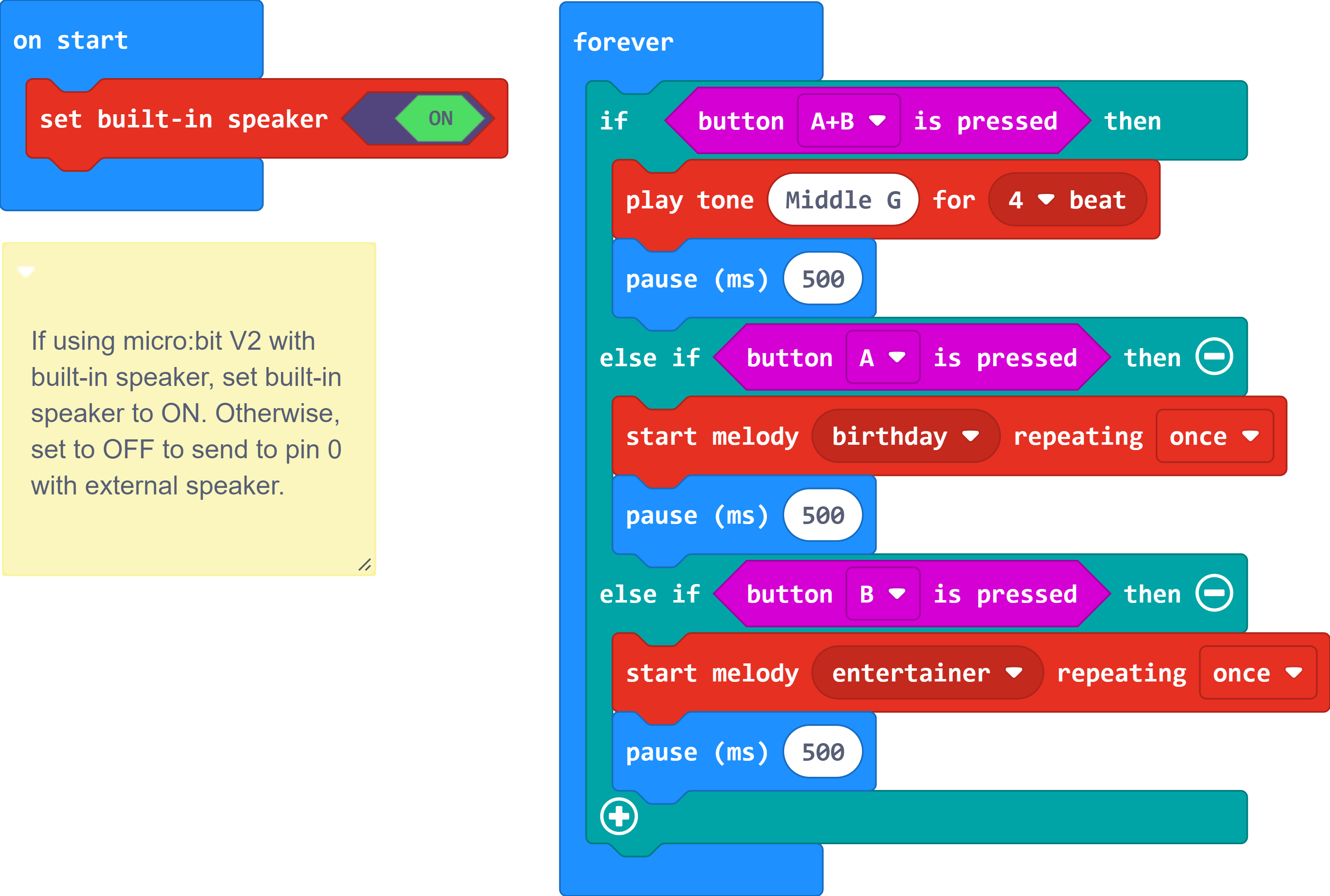
Set Built-in Speaker
The set built-in speaker sets the output for the speaker. By default, this outputs to the built-in speaker on micro:bit v2. Setting it to OFF will output the signal to an external piezo buzzer on pin 0.
Button Pressed
The button pressed block checks the on-board buttons of the micro:bit and allows you to add logic based on whether or not those buttons are pressed.
Play Tone for
The play tone for block is pretty standard if you are used to making sound with other microcontrollers. For example, tone() function in Arduino is pretty much the same as this block. The play tone for block accepts a note that you would like the buzzer to produce and the length of time in beats per second that you would like it to play. So if you are a musician, you are golden to write horrible robot music for your friends!
Start Melody Repeating
The Start Melody Repeating block takes all of the frustration out of getting music out of a microcontroller. It is as simple as selecting one of a number of songs that are preprogrammed into MakeCode and how many times you want it to repeat and you are done! Note that when a melody is playing no other code can run, this is called "blocking" code and has to be accounted for you in your program.
What You Should See
What you should see --- well, nothing! What you should hear --- a song should start as soon as the program starts to run on your micro:bit V1 and a button is pressed! Each button has its own song, and there's another song if you press both buttons at the same time. Enjoy your sound machine and feel free to swap out the song of your choice!
For users with a micro:bit v2, you will hear sound from the built-in speaker once a button is pressed.
Troubleshooting
No Sound
Given the size and shape of the piezo buzzer, it is easy to miss the right holes on the breadboard for users connecting an external piezo buzzer. Try double-checking its placement. Also, make sure that the set built-in speaker is set to the correct position. When using an external piezo buzzer, it must be set to the OFF position. Users with micro:bit v1 will need to delete the code block. Users with micro:bit v2 will neet to set built-in speaker to the ON position.
Feeling Let Down and Deserted
Create your own song using just the tone blocks rather than the standard song options given from the start melody block.
Resources and Going Further
This is just a glimpse into the vast world of micro:bit. We produce a number of other kits and carrier boards that you can hook up to your micro:bit to help take your projects to the next level.
To expand upon the Educator Lab Pack, we recommend the micro:bit Bridge Pack for the full micro:bit Inventor's Kit experience!
For more information on our micro:bit ecosystem, check out these tutorials:
micro:climate Kit Experiment Guide
micro:bot Kit Experiment Guide
micro:arcade Kit Experiment Guide
For additional resources, please check out the following links.
- microbit.org
- About micro:bit - Information about the micro:bit foundation.
- Hardware - Technical and compliance information.
- Quickstart Guide - Additional getting started guides from the micro:bit foundation.
- Activities - Ideas from the micro:bit website.
- Projects - Projects that you can build with your micro:bit.
- Apps - The micro:bit apps let you send code to your micro:bit wirelessly using Bluetooth. No leads needed!
- Educator Teaching Resources - Resources for educators. Classroom oriented activities based on the micro:bit.
- Code Club Activities - 6 activities from Code Club to try out!
- BBC micro:bit - Kitronik University - More micro:bit tutorials.
- SparkFun micro:bit Landing Page
Looking for additional project ideas using just the micro:bit? Check out micro:climate kit's reading light levels experiment:
 |
| micro:climate Experiment 2 - Reading Light Level |
Check out Shawn's 4-part video series with the micro:bit. The projects have examples that use the accelerometer, combines the servo and temperature example, and sends a bluetooth message between two micro:bits. There are two additional videos using micro:bit with MicroPython. Or try exploring micro:bit with cardboard circuits!
Open Source!
All of our experiments and guides are licensed under the Creative Commons Attribution Share-Alike 4.0 Unported License. Feel free to remix and reuse our work. But please, share the love and give us attribution for our hard work!
To view a copy of this license visit this link, or write: Creative Commons, 171 Second Street, Suite 300, San Francisco, CA 94105, USA.