micro:bot Kit Experiment Guide
 D___Run___
 TheDarkSaint
 bboyho
Assembling Your Robot
This section will cover how to assemble your robot chassis. Assembly time: 30-60 minutes
The robot chassis requires the following pieces to build. You'll find most of them in your SparkFun micro:bot kit.

| Letter | Part | Qty |
|---|---|---|
| A | Bottom Chassis Plate | 1 |
| B | Top Chassis Plate | 1 |
| C | Front Motor Mount | 2 |
| D | Rear Motor Mount | 2 |
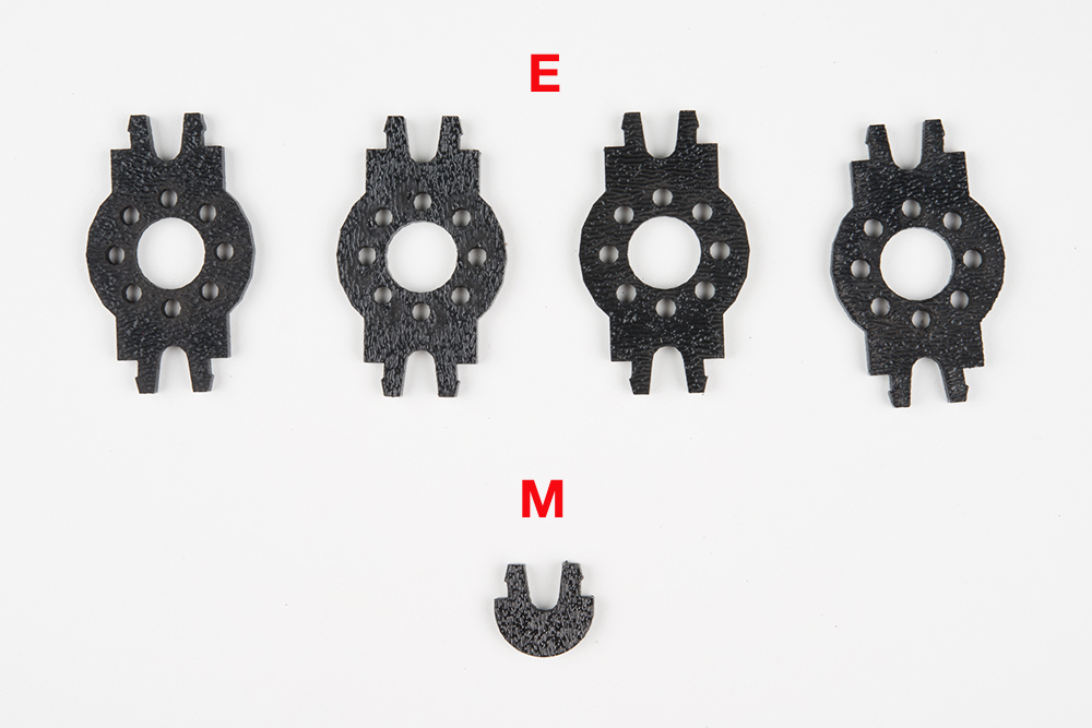
| E | Side Strut | 4 |
| F | Encoder Mount (Not Used in this Guide) | 2 |
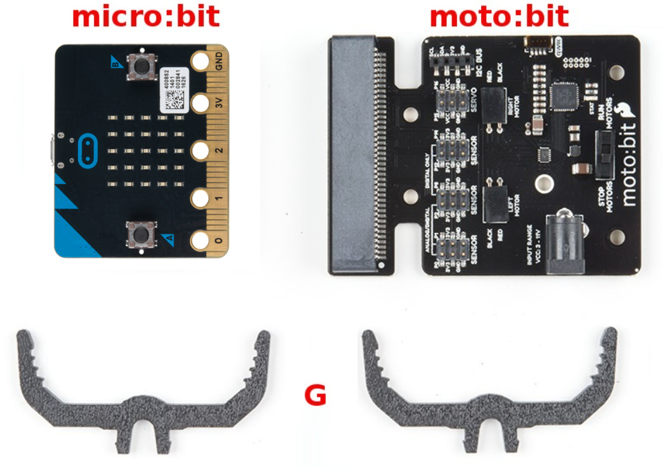
| G | moto:bit Mount | 2 |
| H | Battery Pack Clip | 1 |
| I | Line Follower Mount | 1 |
| J | Line Follower Mount Plate | 1 |
| K | Jumper Wire — 3-pin, 6" | 3 |
| L | Wheels | 2 |
| M | Nub Caster | 1 |
| N | DC Motors | 2 |
| O | Line Follower Boards | 3 |
| P | 4xAA Battery Holder | 1 |
| Q | 4xAA Batteries (Not Included) | 3 |
No Tools Necessary
The robot chassis does not require any additional tools.

A Note About Orientation
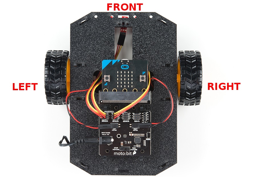
When we talk about the "front," "left," "right," and "back" of the Shadow Chassis, we are referring to specific sides of the robot when viewed from above.
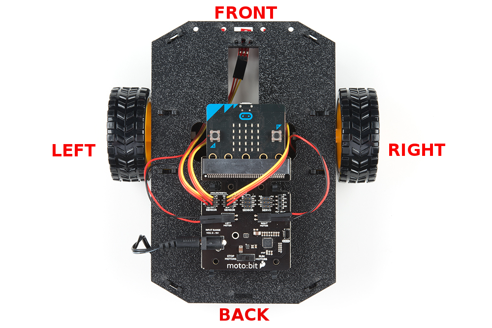
Notice that we consider the SparkFun moto:bit to be on the "back" of the bot and the Bumper Whiskers and Line Follower Boards to be in the "front."
Assembly
Installing Motors
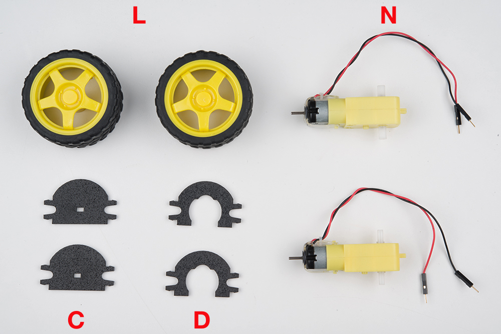
Let's begin by installing the motors that will control the wheels. Locate the following:
Attach Rear Motor Mounts
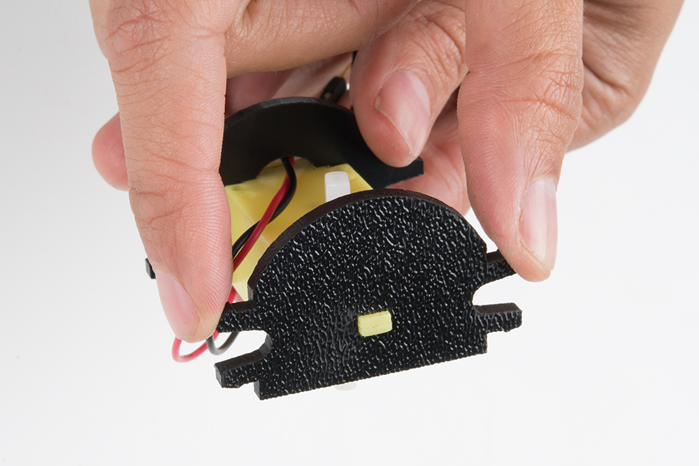
Hold the wires near the middle of the Motor (N), and carefully slide a Rear Motor Mount (D) in from the side and over the two motor wires. Be careful not to snag the wires, the cable tie, or the clear plastic strap.
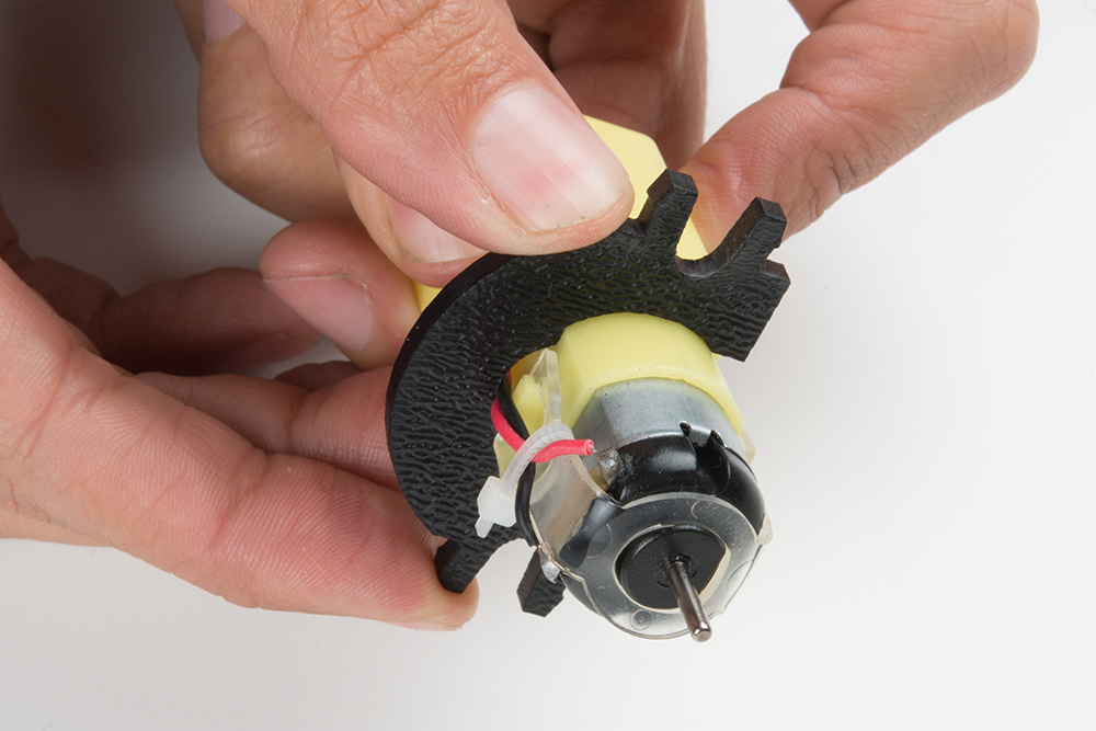
Holding the motor wires, gently twist the Rear Motor Mount counter clockwise so that it snaps in place on the motor and the wires are centered in the gap of the motor mount. Again, be sure not to snag the wires under the motor mount.

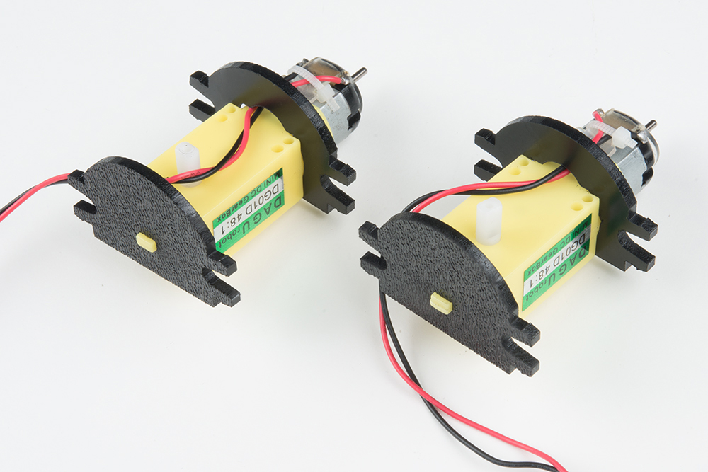
Repeat the process for the second motor, ensuring that it is a mirror image of the first.
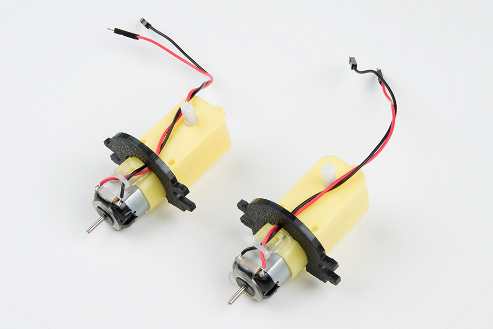
Attach the Front Motor Mounts
Slide a Front Motor Mount (C) onto the protruding eyelet on the front of a Motor (N). Ensure the rounded sides of the motor mounts are facing the same way.
Repeat the process for the second motor.
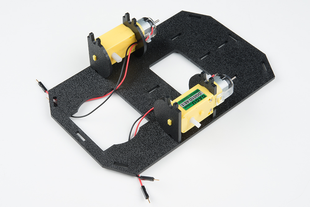
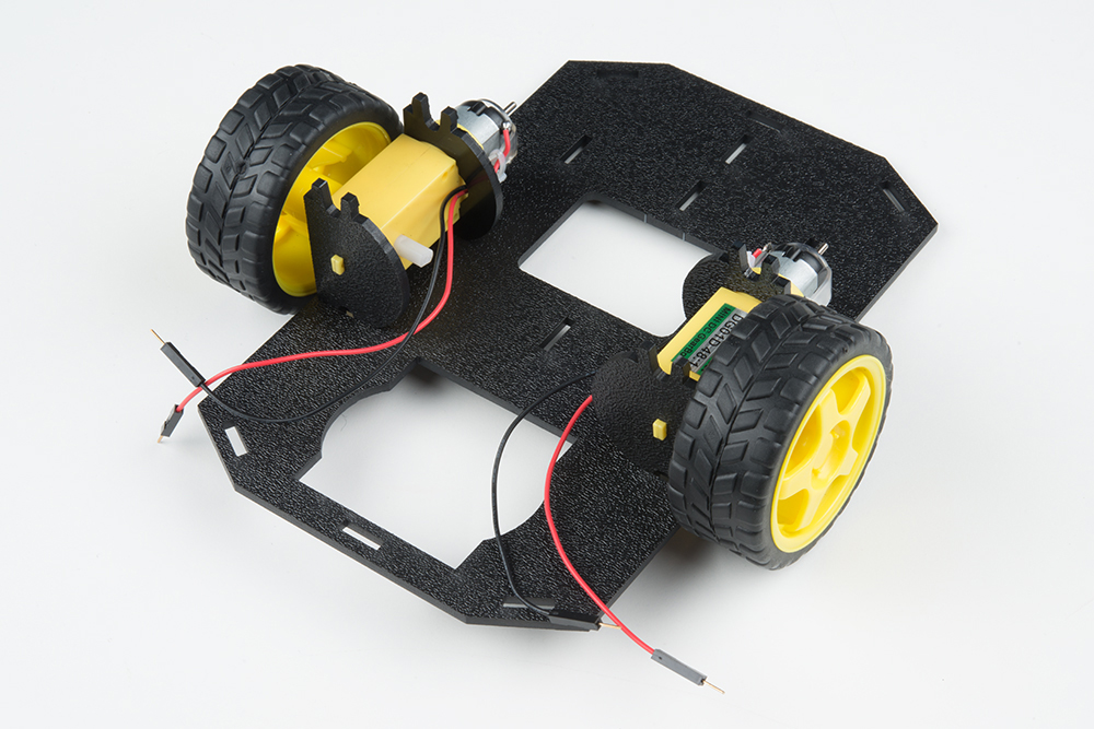
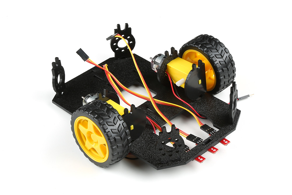
Attach the Motor Assemblies to the Chassis
Snap one of the motor assemblies into the left two horizontal slots of the Bottom Chassis Plate (A). Make sure that the rounded edges of the motor mounts and the wires are facing toward the center of the chassis. Repeat for the opposite motor.
Attach the Wheels
Slide one Wheel (L) onto the plastic shaft of a Motor (N). Look at the motor shaft. Notice it has two flat edges. Make sure to line up the flat edges of the motor shaft with the flat edges of the wheel.
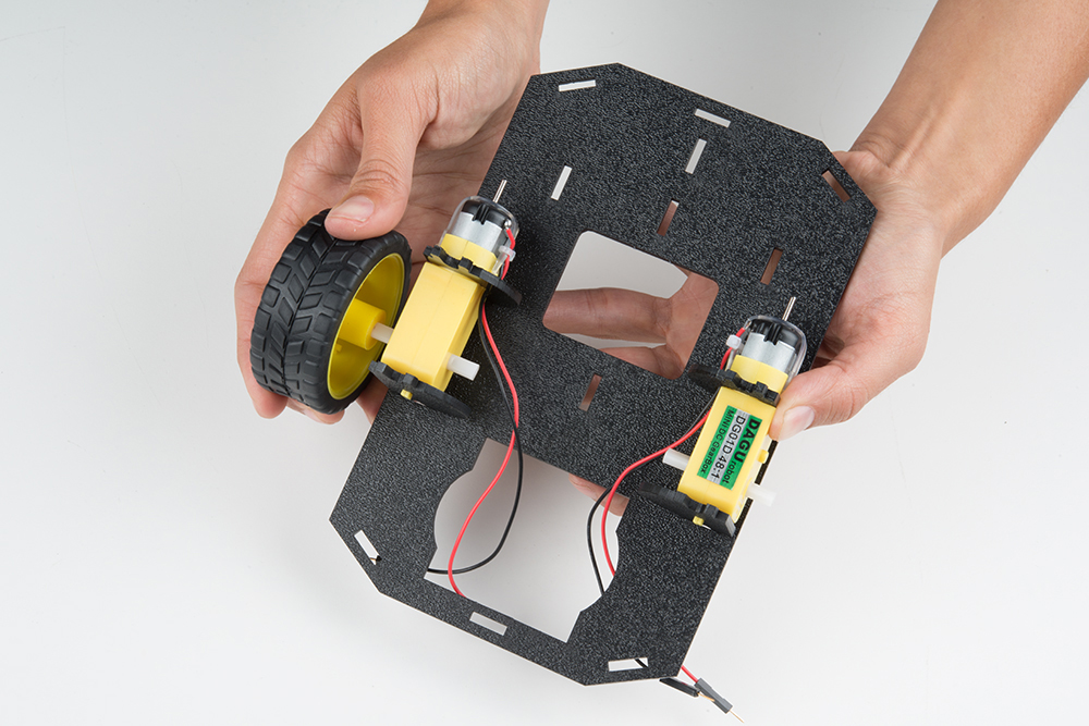
Repeat with the other wheel.
Installing the Line Sensors
This section will cover the Line Following Sensors array assembly. You'll first build the Line Following array and then attach it to the chassis. Locate the following:

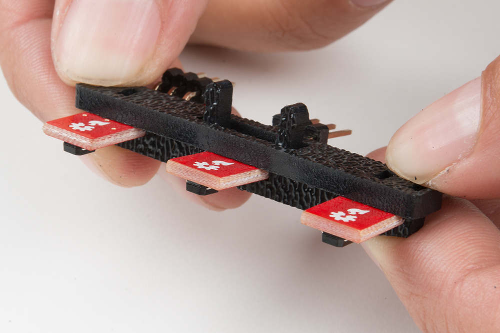
Construct the Line Follower Assembly
Attach the three Line Follower Boards (O) to the Line Follower Mount (I) such that the rectangular pegs in the Line Follower Mount poke through the mounting holes in the Line Follower Boards. Make sure the sensors are facing away/down from the clip of the mount.
Place the Line Follower Mount Plate (J) on top of the Line Follower Mount (I) so that the center clip of the mount is poking through the center slot of the plate.
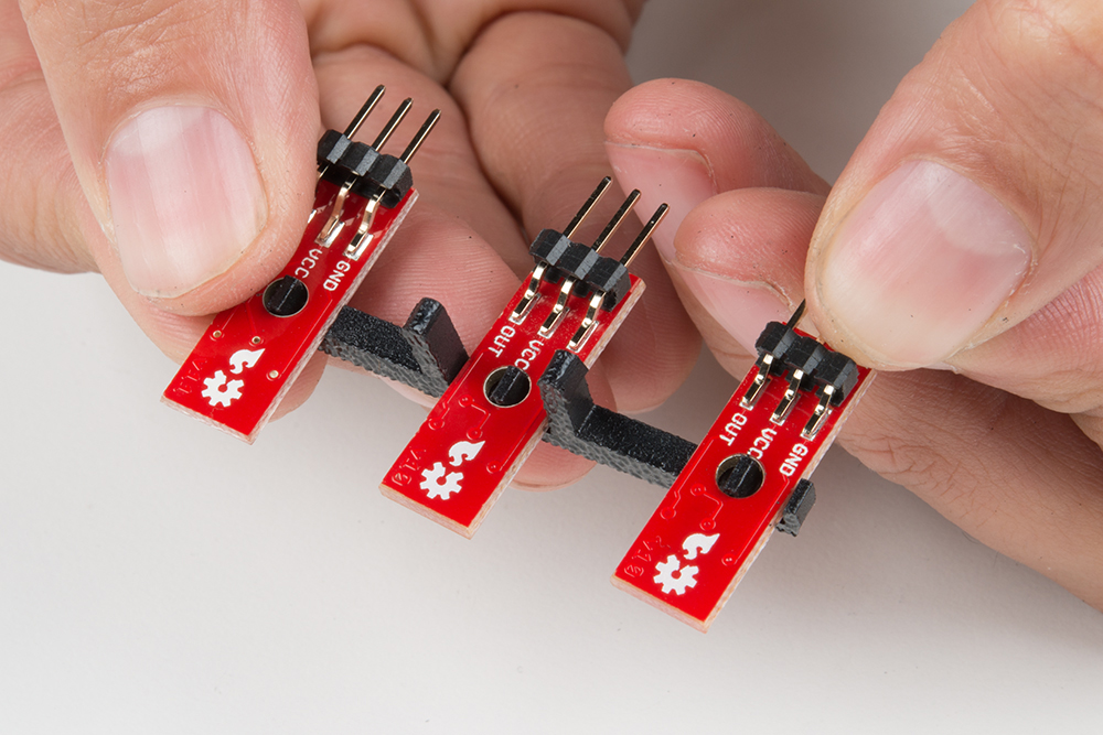
Attach the Cables
You will need to connect a 3-Wire Jumper Cable (K) to each of the Line Follower Boards (O). Note the color of the wire attached to each pin.
Line Follower Connections:
| Jumper Wire Color | RedBot Sensor - Line Follower |
|---|---|
| Red | GND |
| Orange | VCC |
| Yellow | OUT |
Attach all 3 cables to the 3 Line Follower Boards. Notice that the yellow wire should be on the right (out) and the red wire should be on the left (ground).

Attach the Line Follower Assembly to the Chassis
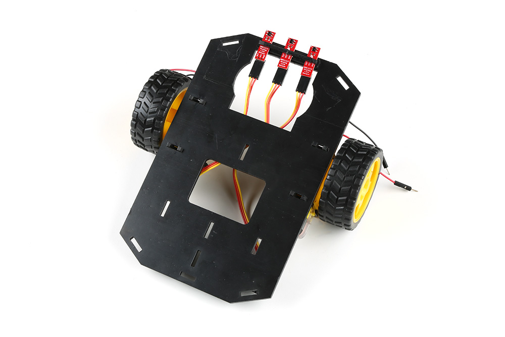
Locate the wide, rectangular slot near the front of the chassis and snap the line follower assembly in from the bottom side of the chassis. Route the cables through the large hole in the bottom plate.
The bottom of your chassis should look like the following image allowing the line sensors to be facing down.
Final Assembly
With the motors and a few sensors attached, we can assemble the main body of the robot. Locate the following:
You will also need the Top Chassis Plate and Bottom Chassis Plate assemblies, which have any additional parts and sensors you attached in previous steps.
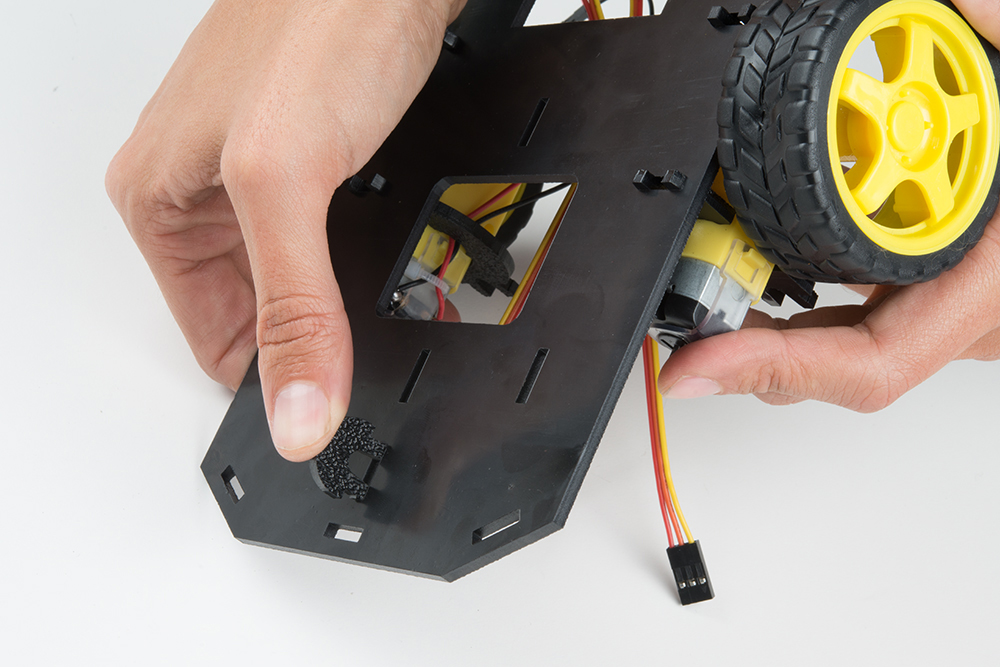
Attach the Nub Caster
Snap the Nub Caster (M) into the slot on the back of the Bottom Chassis Plate assembly. Make sure the Nub Caster is on the side opposite the motors (the bottom side).
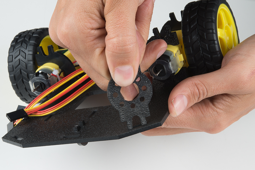
Add the Side Struts
Snap the four Side Struts (E) into the diagonal slots on the four corners of the Bottom Chassis Plate assembly.
Pull the cables through the cutouts on the chassis.
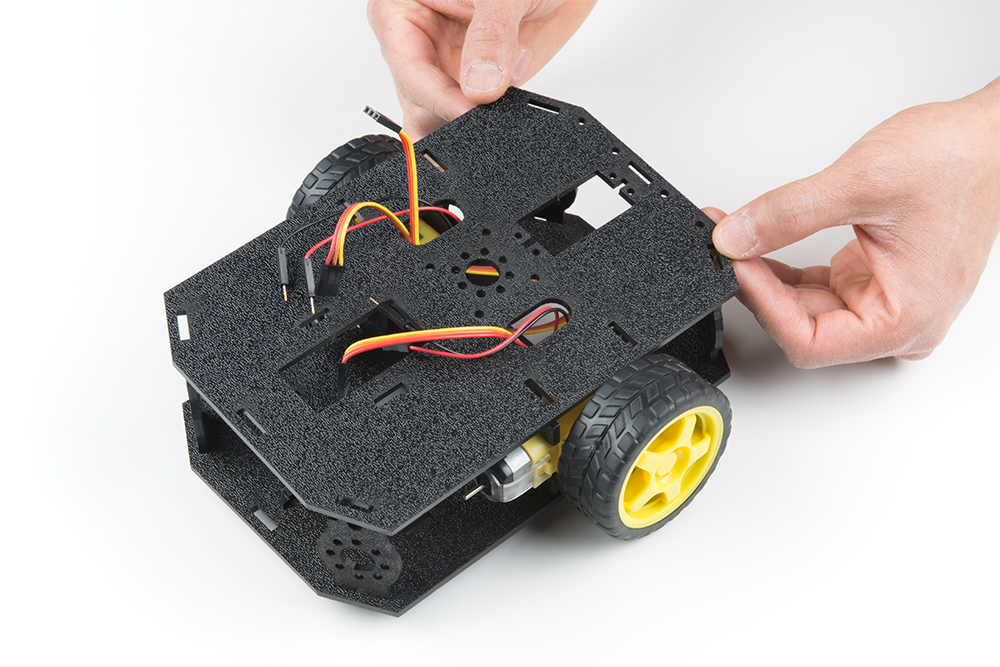
Route the Cables
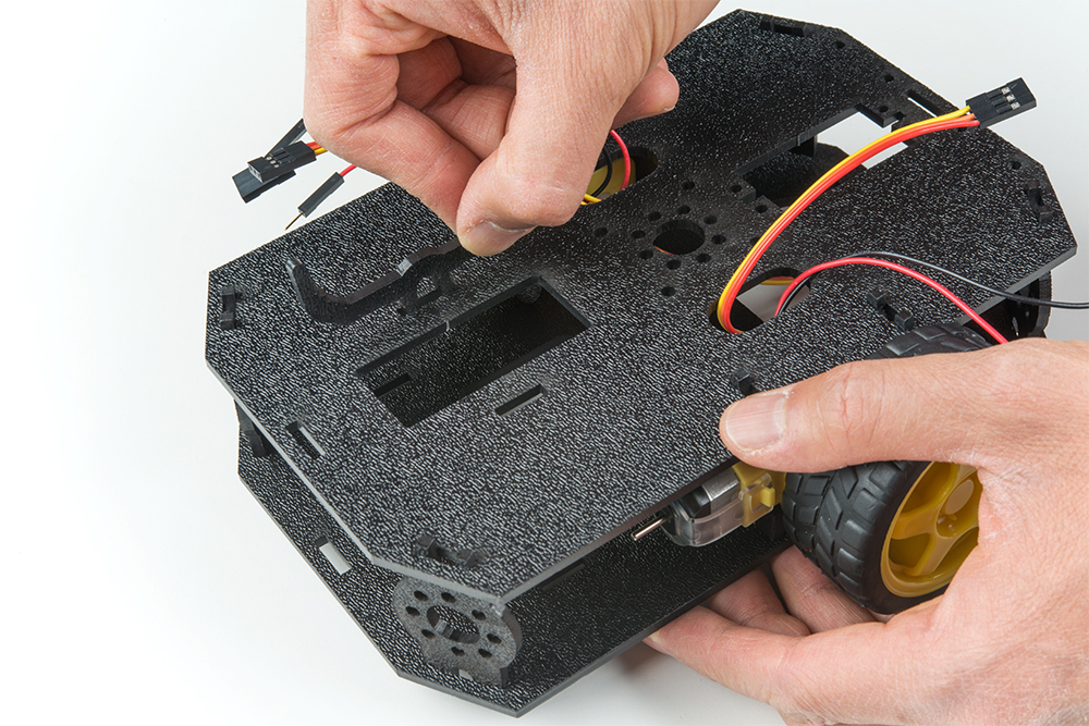
Position the Top Chassis Plate over the Bottom Chassis Plate -- but do not snap the two plates together yet. Make sure that the front sides of each plate line up.
Route the wires and cables through the left and right oval slots in the Top Chassis Plate assembly as shown. For the center line follower sensor, route this cable through the left oval slot.
Cable Routing:
| Cable Connection | Oval Side |
|---|---|
| Left Line Follower | Left |
| Center Line Follower | Left |
| Right Line Follower | Right |
| Left Motor Wires (red and black) | Left |
| Right Motor Wires (red and black) | Right |
Attach Top Chassis Plate Assembly
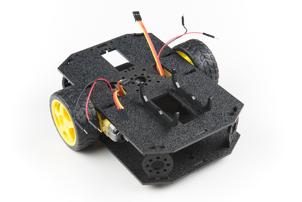
Line up the Top Chassis Plate on top of all the struts, and carefully snap the Top Chassis Plate assembly onto the side struts and motor mounts. Press gently above each side strut individually until they each snap into place. If you have the Bumpers installed, make sure the boards are between the top and bottom plates.
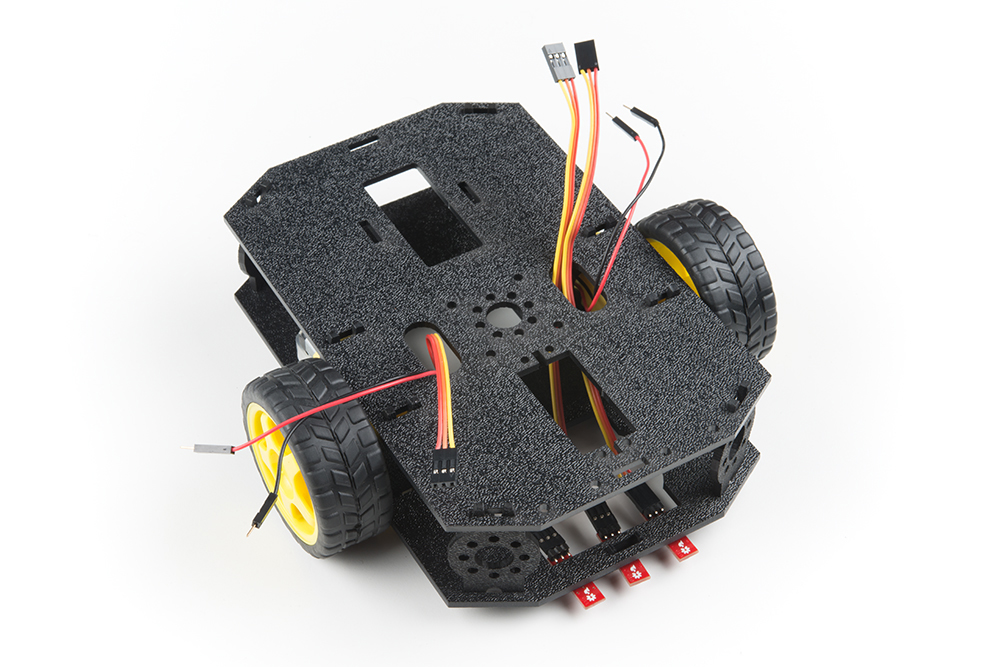
If you need to remove the plate to change anything, gently pull upward on each side strut individually. Do not attempt to use pliers or hand tools, or you may end up snapping the plastic clip.
Attaching the moto:bit
In this section, you will add brains of the robot: the micro:bit and SparkFun moto:bit. Locate the following:
You will also need the full chassis assembly, which contains any additional parts you attached in previous steps.
Attach the moto:bit Mounts
Snap the two moto:bit mounts (G) into the vertical slots in the back of the top chassis plate near the large rectangular opening.
Both of these mounts will enable your moto:bit board to be mounted to the chassis.
Add the moto:bit
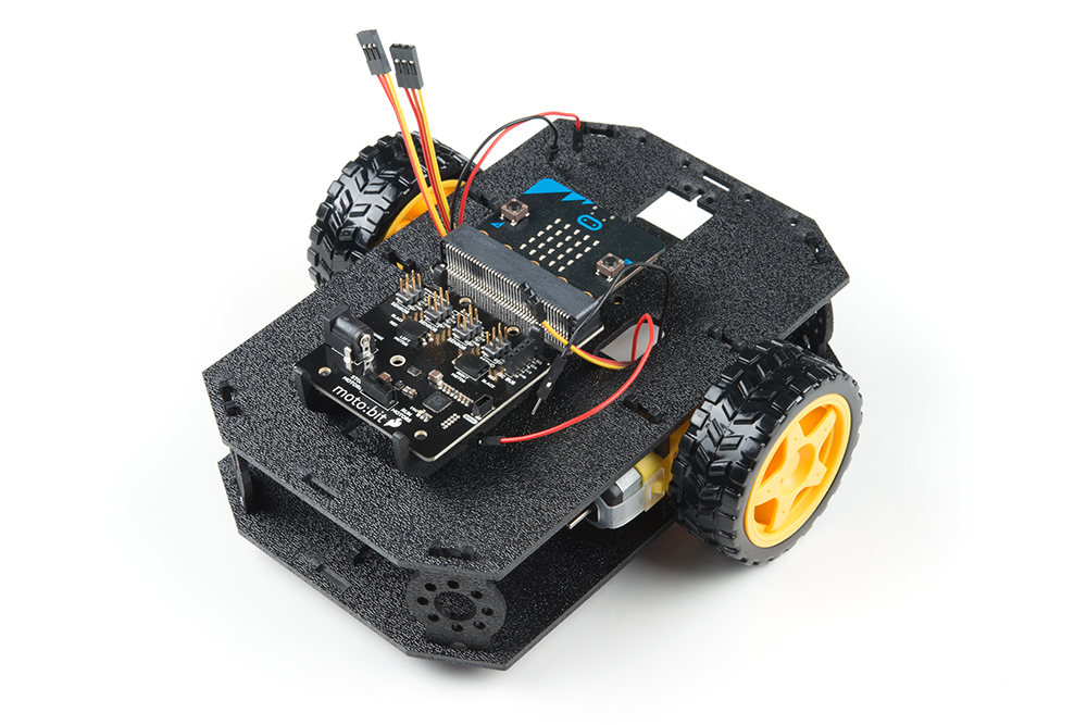
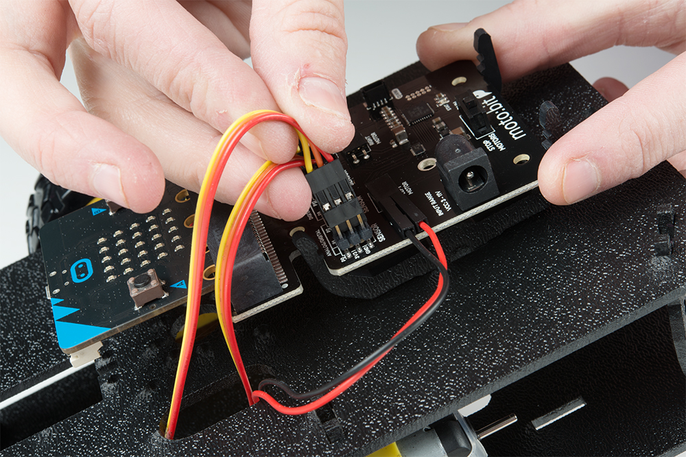
Before you snap in the moto:bit board, insert your micro:bit into the moto:bit as shown here.

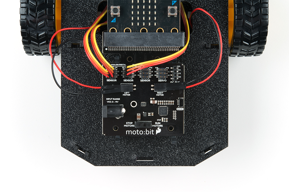
The moto:bit snaps into the lowest of the notches on the moto:bit Mounts (G). Make sure the power jack is facing the left side of the robot. Push gently and evenly until it snaps into place.

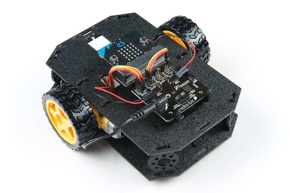
Once snapped, your setup should look like the image below without the wires connected to the moto:bit board
Connecting the Cables
It is time to connect the jumper wires; it is really important that these connections are right.
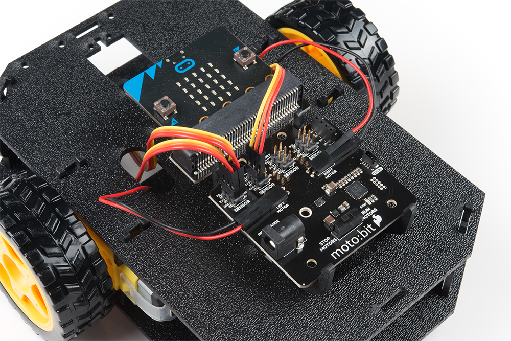
Follow along with the tables and annotated image with the cables connected for reference. Trace each cable poking through the top chassis plate to make sure you know what it is connected to.
Line Followers
Below is a table for each connection between moto:bit and analog line follower. Start with the left line follower.
Left Line Follower:
| SparkFun moto:bit Pins | Jumper Wires | Left Line Follower Board |
|---|---|---|
| P0 | 3-Wire Jumper Cable - Yellow | OUT |
| 3.3V | 3-Wire Jumper Cable - Orange | VCC |
| GND | 3-Wire Jumper Cable - Red | GND |
Center Line Follower:
| SparkFun moto:bit Pins | Jumper Wires | Center Line Follower Board |
|---|---|---|
| P1 | 3-Wire Jumper Cable - Yellow | OUT |
| 3.3V | 3-Wire Jumper Cable - Orange | VCC |
| GND | 3-Wire Jumper Cable - Red | GND |
Right Line Follower:
| SparkFun moto:bit Pins | Jumper Wires | Right Line Follower Board |
|---|---|---|
| P2 | 3-Wire Jumper Cable - Yellow | OUT |
| 3.3V | 3-Wire Jumper Cable - Orange | VCC |
| GND | 3-Wire Jumper Cable - Red | GND |
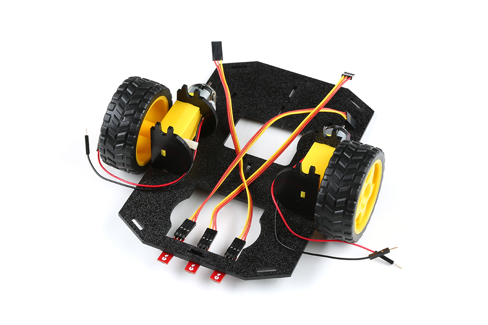
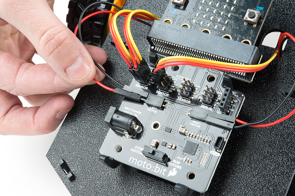
Once connected, the wires should look similar to the image below.
Motors
Choose a pair of motor wires to begin wiring up to the moto:bit. The way the motors are wired up to the moto:bit will affect how the micro:bot drives. Make sure to follow the color of the wire with the silkscreen on the board.
Below is a table for each connection between moto:bit and motor.
Left Motor:
| SparkFun moto:bit Pins | Left Motor Jumper Wires |
|---|---|
| LEFT MOTOR - RED | Soldered on Motor Jumper Wire - RED |
| LEFT MOTOR - BLACK | Soldered on Motor Jumper Wire - BLACK |
Right Motor:
| moto:bit Pins | Right Motor Jumper Wires |
|---|---|
| RIGHT MOTOR - RED | Soldered on Motor Jumper Wire - BLACK |
| RIGHT MOTOR - BLACK | Soldered on Motor Jumper Wire - RED |
Once all wires are connected it should look like the following image.
 |
 |
| "Correct" Motor Wiring | "Incorrect" Motor Wiring |
Batteries
The last step is to provide a power source for the micro:bot. You will need to provide your own AA batteries (Q). Locate the following:
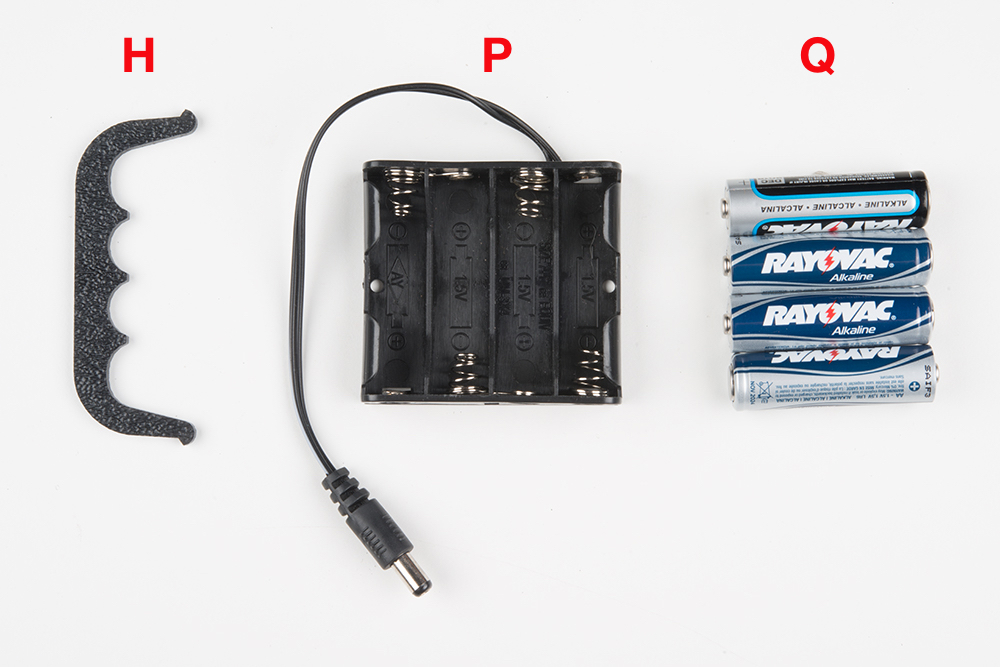
Insert Batteries
Insert the AA batteries into the Battery Holder (P). Makes sure the batteries are facing the correct direction, as per the markings inside of the Battery Holder.

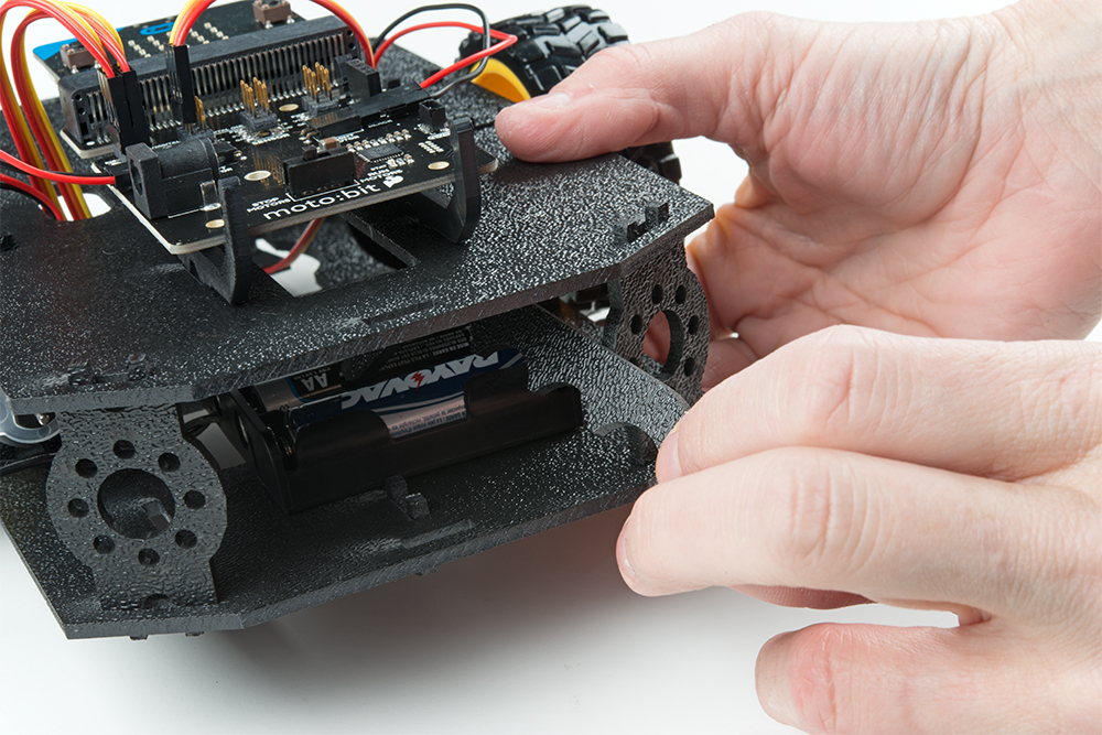
Attach Battery Pack
Insert the Battery Holder (P) with batteries into the back cavity of the chassis. Position the Battery Holder so that the barrel jack cable comes out on the left side of the robot.

Insert the Battery Pack Clip (H) on top of the battery pack.
Twist and position the clip so that it rests on top of the battery pack.
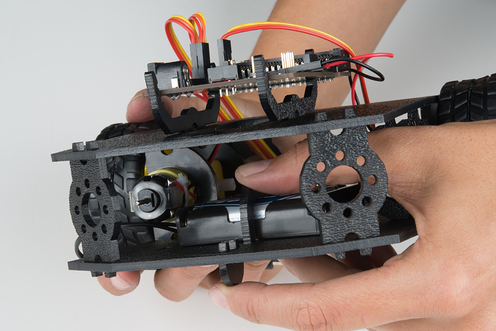
Push the clip down into the vertical slots in the Bottom Chassis Plate so it snaps in place.
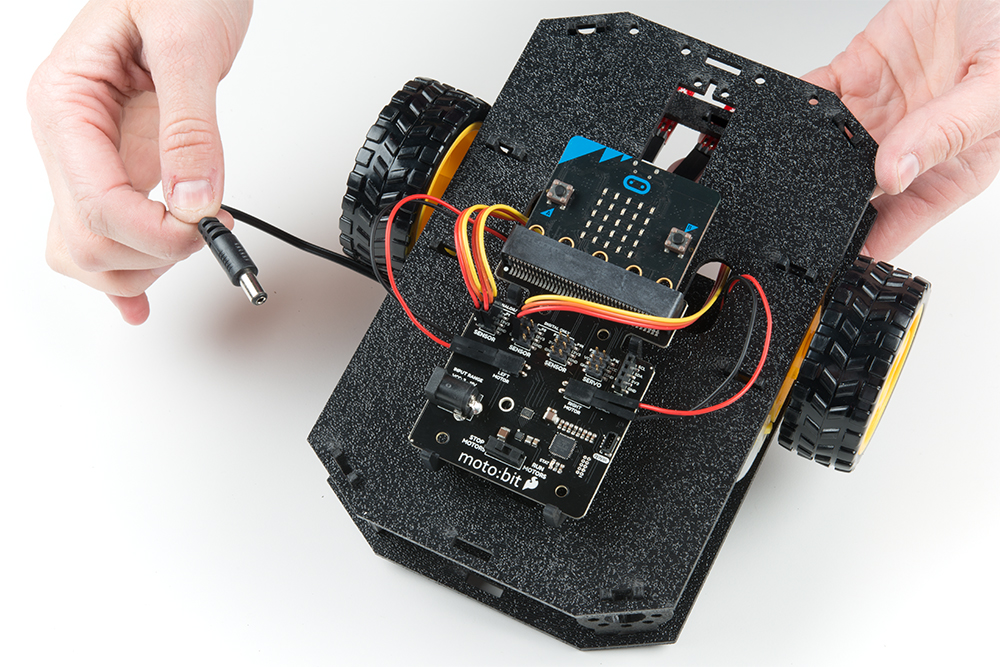
Route the barrel jack cable out of the left side of the chassis and up to the moto:bit.
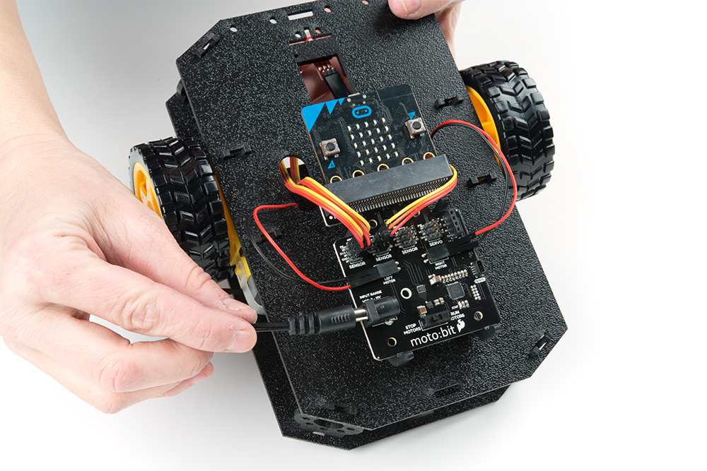
Plug the barrel jack cable into the barrel connector on the side of the moto:bit carrier board.
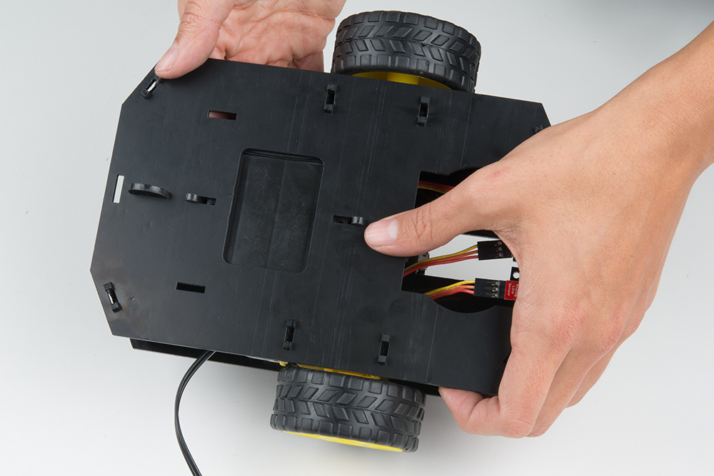
Changing the Batteries
If you find that you need to replace the batteries in the micro:bot, the process is simple. Unplug the battery pack from the moto:bit.
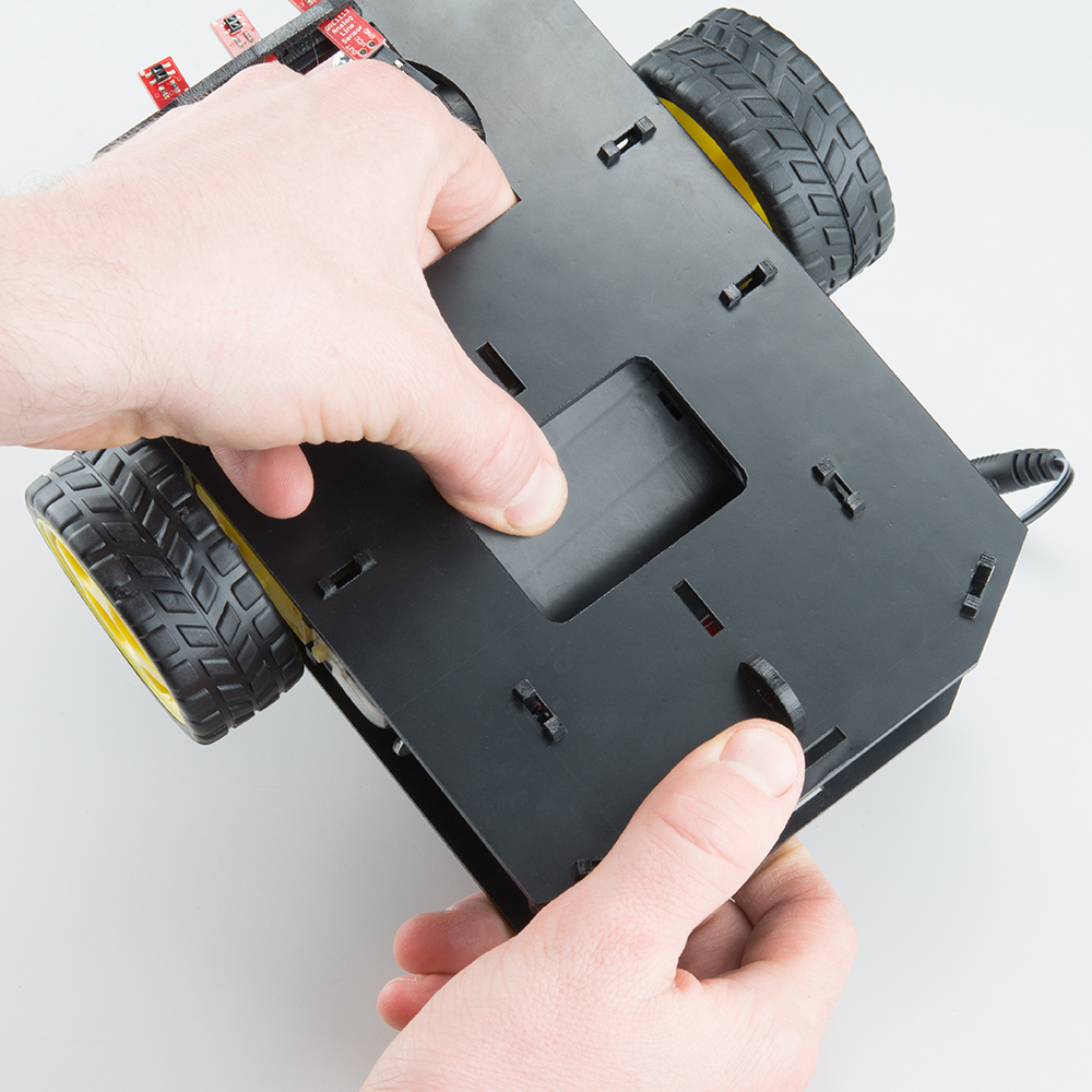
Turn the micro:bot over and push on the Battery Holder through the hole in the Bottom Chassis Plate. This will cause the Battery Pack Clip to unsnap from the Bottom Chassis Plate.
Slide the Battery Pack and Clip out from the back of the micro:bot.
Change the batteries, and follow the steps in Attach Battery Pack section above to put the Battery Pack back in the micro:bot.