micro:bot Kit Experiment Guide
 D___Run___
 TheDarkSaint
 bboyho
Experiment 2: Staying in a Box
Introduction
Robots are smart! They are smart because they use sensors to detect what the world around them and then respond to those conditions. One of the conditions our robot can respond to is the darkness of the surface that it is driving on. It can detect lines, a gradient of darkness or a blacked out area. In this experiment you will program your robot to stay inside of a box that you have drawn on a surface.
Parts Needed
You will need the following parts:
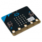
- 1x micro:bit board (Not Included with Kit)
- 1x Micro-B USB Cable (Not Included with Kit)
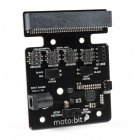
- 1x moto:bit Carrier Board
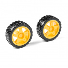
- 2x Wheels
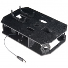
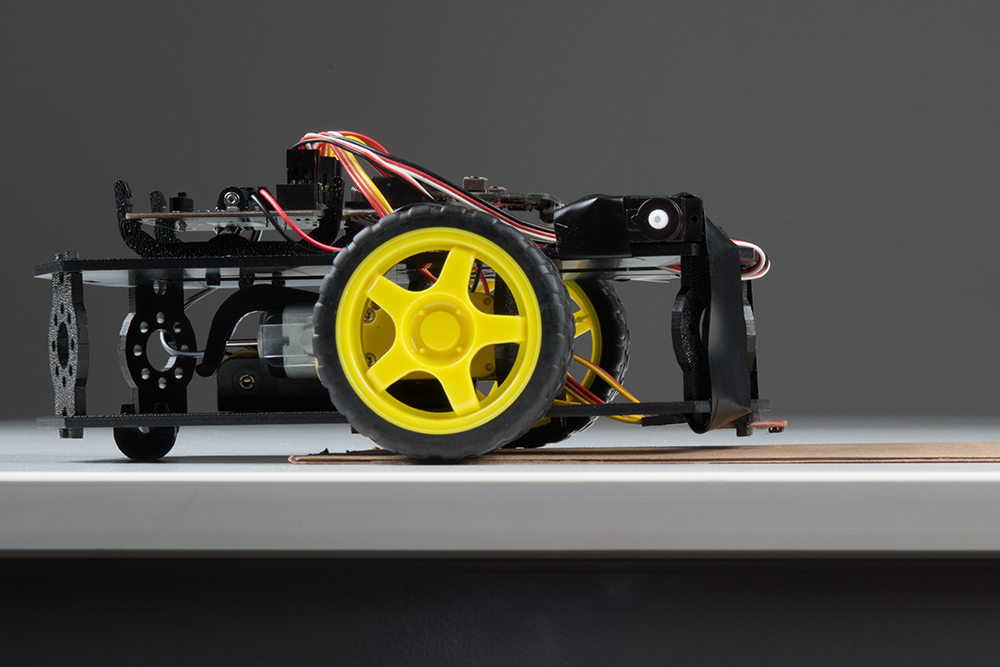
- 1x Assembled Shadow Chassis
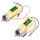
- 2x Hobby Gear Motors
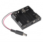
- 1x 4xAA Battery Holder
- 4x AA Batteries (Not Included with Kit)
- 3x Analog Line Following Sensors
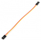
- 3x 3-Pin Jumper Wires
Didn’t get the kit? Have no fear! Here are the parts you will need to complete this experiment. You may not need everything though depending on what you have. Add it to your cart, read through the guide, and adjust the cart as necessary.


Suggested Reading
Before continuing on with this experiment, we recommend you be familiar with the concepts in the following tutorial:
Getting Started with the micro:bit
Introduction to the Line Sensors
The line follower sensor is an add-on for your shadow chassis that gives your robot the ability to detect lines or nearby objects. The sensor works by detecting reflected light coming from its own infrared LED. By measuring the amount of reflected infrared light, it can detect transitions from light to dark (lines) or even objects directly in front of it.
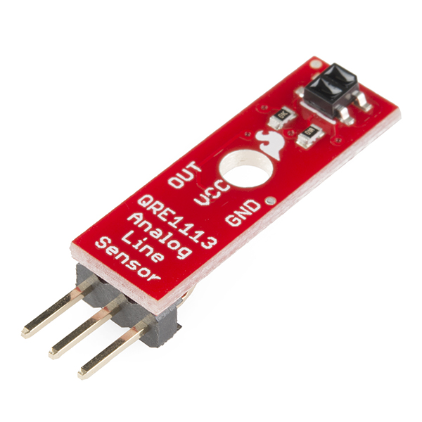
The sensor has a 3-pin header which connects directly to the moto:bit carrier board via female to female jumper wires. A mounting hole lets you easily connect one or more of these to the front or back of your robot chassis.
The IR Reflectance sensors work best when they are close to the surface below the micro:bot. The sensor should be about 1/8" above the table. This is an optimal distance for the IR transmitter to illuminate the surface below and measure the reflected light. (Note: Human eyes are non sensitive to IR light, but if you use a CCD camera -- like the one in your phone -- you can see a small light shining out of the front element).
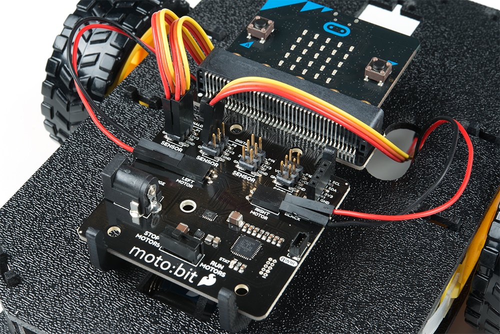
Hardware Hookup
Like the motors, you should have already hooked up the line sensors during the assembly portion of this guide. You can go there now for the full assembly instructions. Double check to make sure that the wires are hooked up to your line sensors correctly!

The line sensors hookup to your moto:bit via female / female jumper wires that snake through the chassis of your robot up to the moto:bit. The sensors hookup to the moto:bit in the following order:
- LEFT =>
P0 - CENTER =>
P1 - RIGHT =>
P2
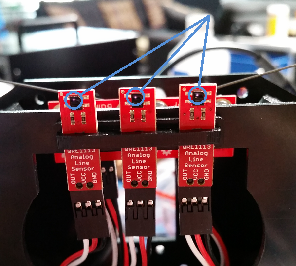
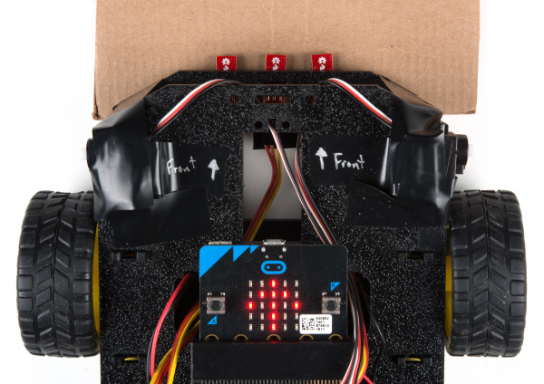
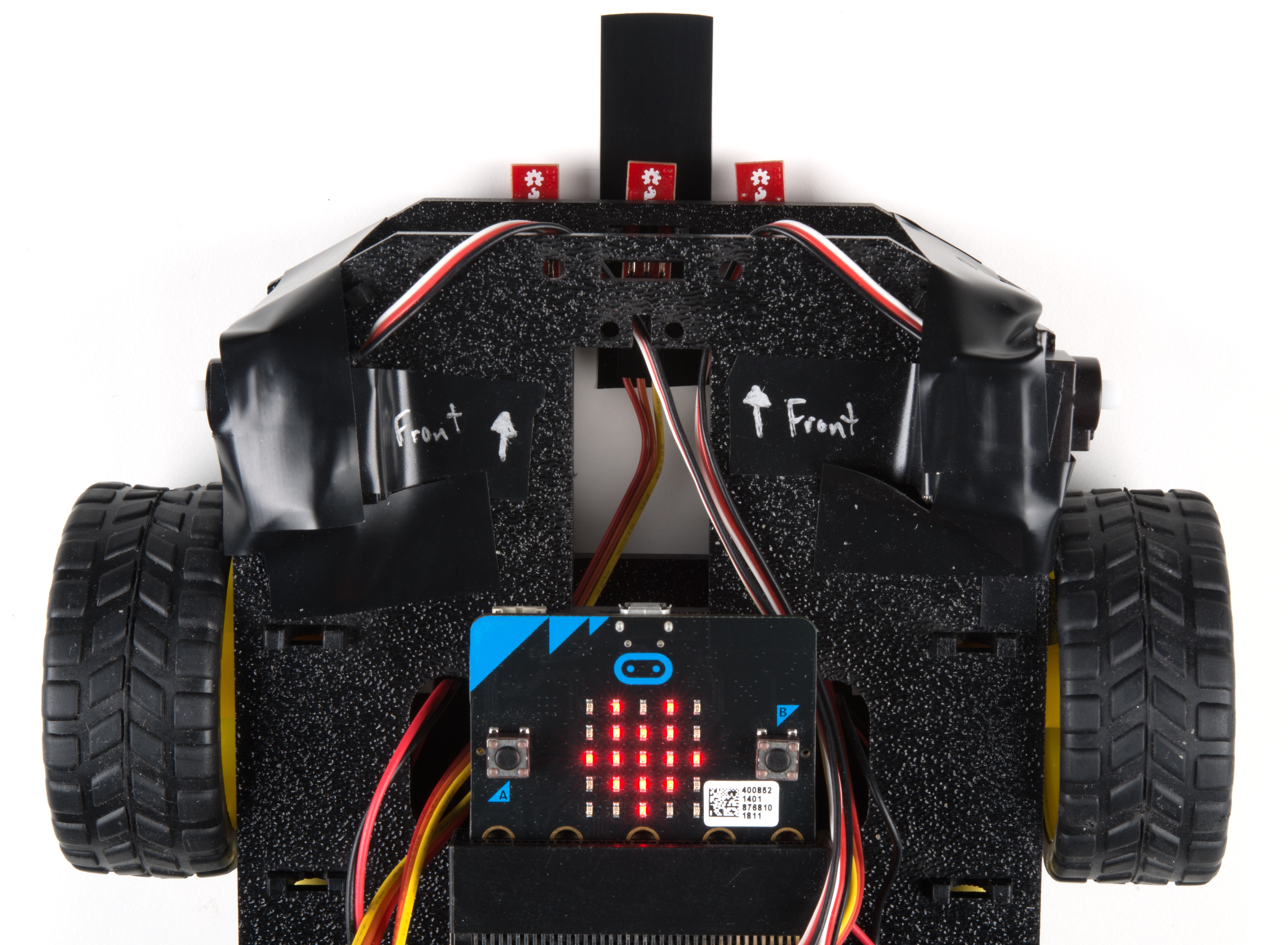
Double check to make sure they are hooked up correctly and in the proper orientation:
Running Your Script
Be sure to add the moto:bit package as instructed in the Installing the moto:bit Package in MakeCode section of this tutorial.
Now, you can either download the following example script below and drag and drop it onto your micro:bit, or use it as an example and build it from scratch in MakeCode.
Code to Note
Let's take a look at the code and what to expect.

Initialize Serial Output
When the code first starts, we initialize a serial output on the micro:bit to send serial to the USB. Using the serial redirect to USB code block defaults the 115200 baud. This is useful whenever we need to inspect the sensor readings and interpret the values in a serial terminal.
Set Motors
We will need to set the motors depending on how the motors are wired to the moto:bit. In this case, we will be setting both motors to true to be consistent with how we assembled the robot earlier.
Creating a Variable
In Microsoft MakeCode, you need to be able to create variables to store information for your robot to compare against, or to just remember. You can use the built-in variables under the Variables drawer as shown below.
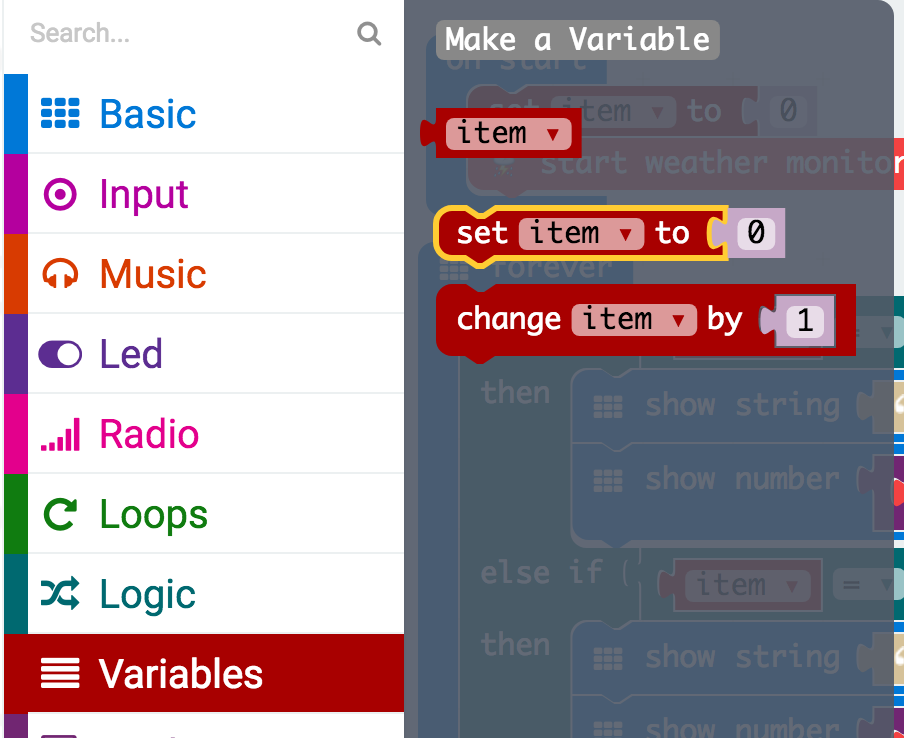
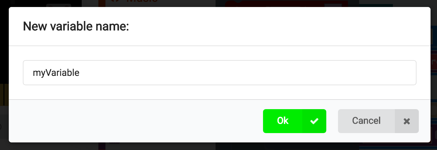
But, you can also make your own custom variables. To do this click on the Variables drawer and select Make New Variable. You can then name it and use it in your program. In this case, we are going to create two new variables. One to have the micro:bit remember what our black line looks like (i.e. black_line) and another for the current sensor reading (current_surface_reading).
Set To
To store a value or piece of information in a variable you use the set _______ to block. This allows you to select a variable and set it to a value or block of your choice. In this case, the line following sensor value connected to pin P1. We do this once in the on start block to get a base reading from the sensor so that our micro:bit remembers the value of the black line. This calibrates the sensor for the micro:bot. Pressing button A while the program is running will also save the line sensor reading again.
Analog Read Pin
To get that base reading from the line sensor we use the analog read pin __ block to get an analog value (0 - 1023) from the line sensor.1023 is totally black and 0 is totally saturated white. Your surface will be something probably in between.
If Condition Statements
To compare the current reading of the line sensor to its known baseline value that was captured and stored in the on start block, we use an if statement block. The if block accepts a logical statement. If that statement (current_surface_reading ≥ black_line - 100) is true, then the if block runs then "then" section of code. If that statement is false, then the "else" section of the block is run.
You may be asking yourself why subtract 100 from the surface value. Well, that number is a sensitivity value. The sensor reading fluctuates as the robot moves around and when the motors are running. By subtracting 100 from the original surface variable, we give the change in lighting a "wiggle room" or tolerance of 100. If you want your sensor to be more sensitive, you would make the number smaller. If you need it less sensitive, make it bigger.
To debug, we'll send serial to the USB before the condition statement and animate the LEDs of the micro:bit within each condition statement show icon _____ (or show leds _____) block to help visualize when the micro:bot moves forward, back, or to the left.
What You Should See
Serial Output
You can pair, upload code to the micro:bit, and view the output on the MakeCode console without having to drag and drop the file to the micro:bit after updating the firmware. For more information about using the WebUSB feature on MakeCode, make sure to check out the instructions provided by micro:bit support.
Otherwise, you can use your favorite serial terminal or program to real time, serial data plotter to graph the output.
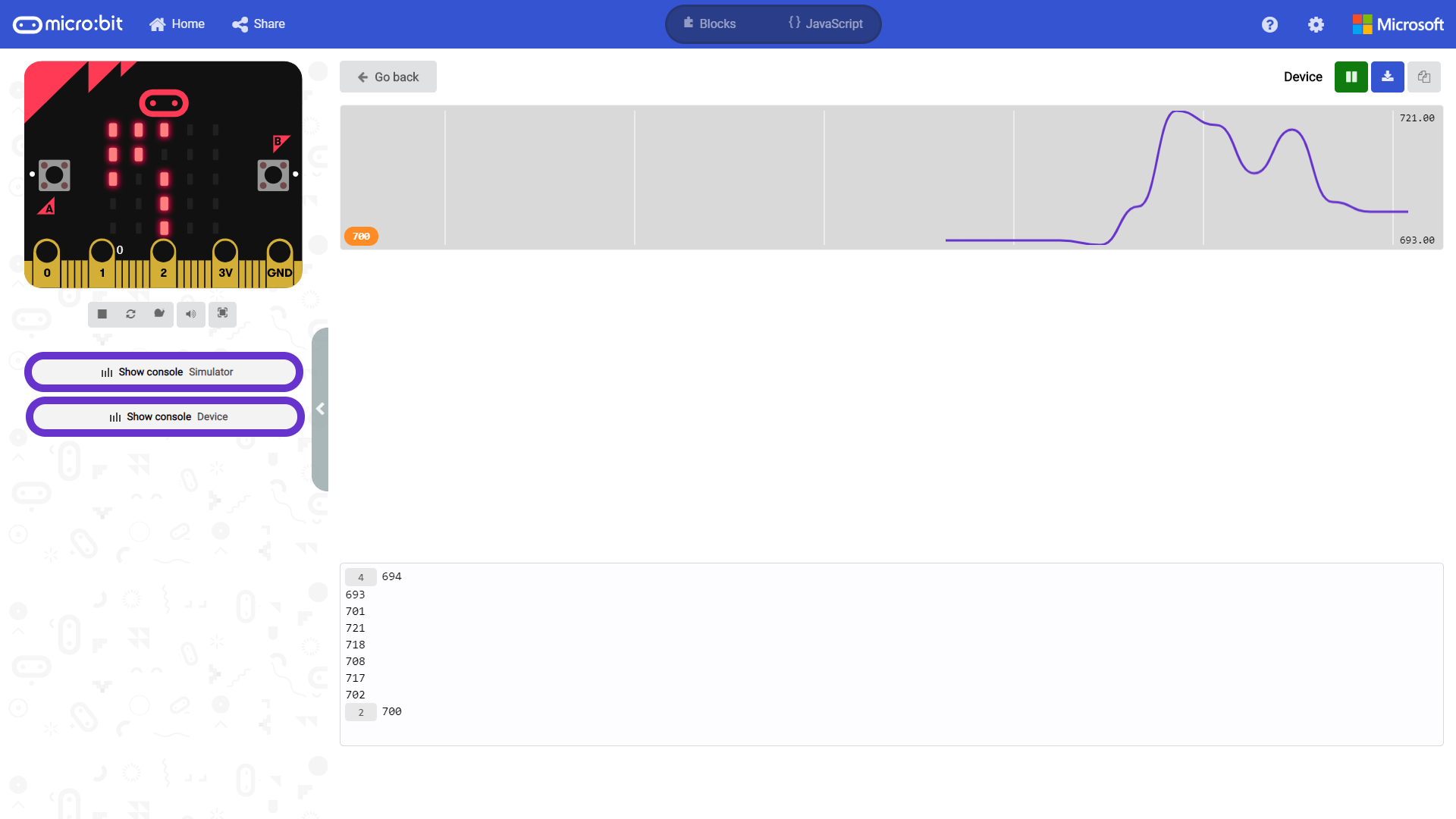
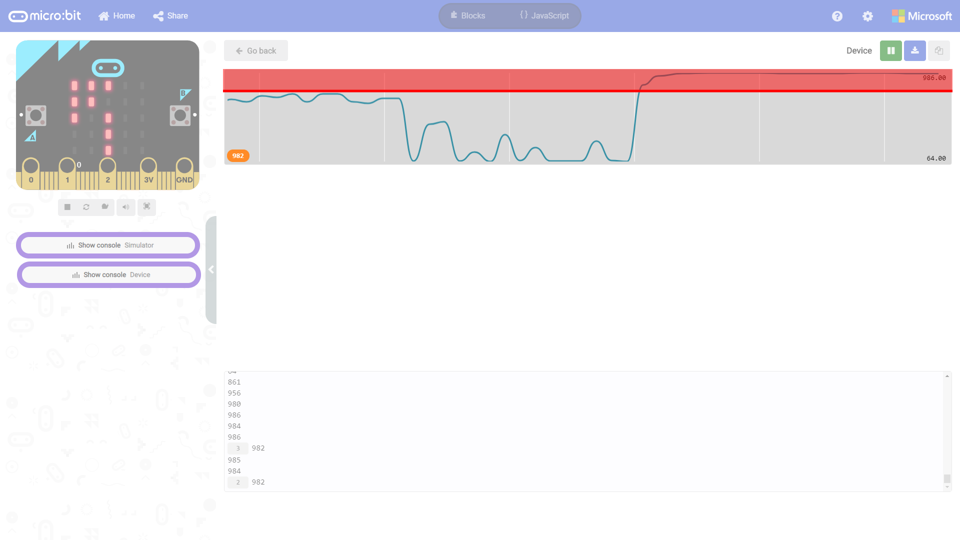
For the scope of this tutorial, we'll use the MakeCode console to output the serial output. If you have paired the micro:bit to your computer and used the one-click download feature for MakeCode, a "Show console Device" button should appear in MakeCode. Click on the button to view the serial output. A graph and serial monitor will appear over the MakeCode code editor. This is due to the graph automatically resizing. You may notice that there is no data graphed and a number on the bottom left. The serial monitor will also display a number with a counter. The counter indicates how many times we output the same value. Try moving the line following sensor around the surface of a table. Keep in mind that the micro:bit in the simulator does not reflect the LEDs on the physical micro:bit in real-time.
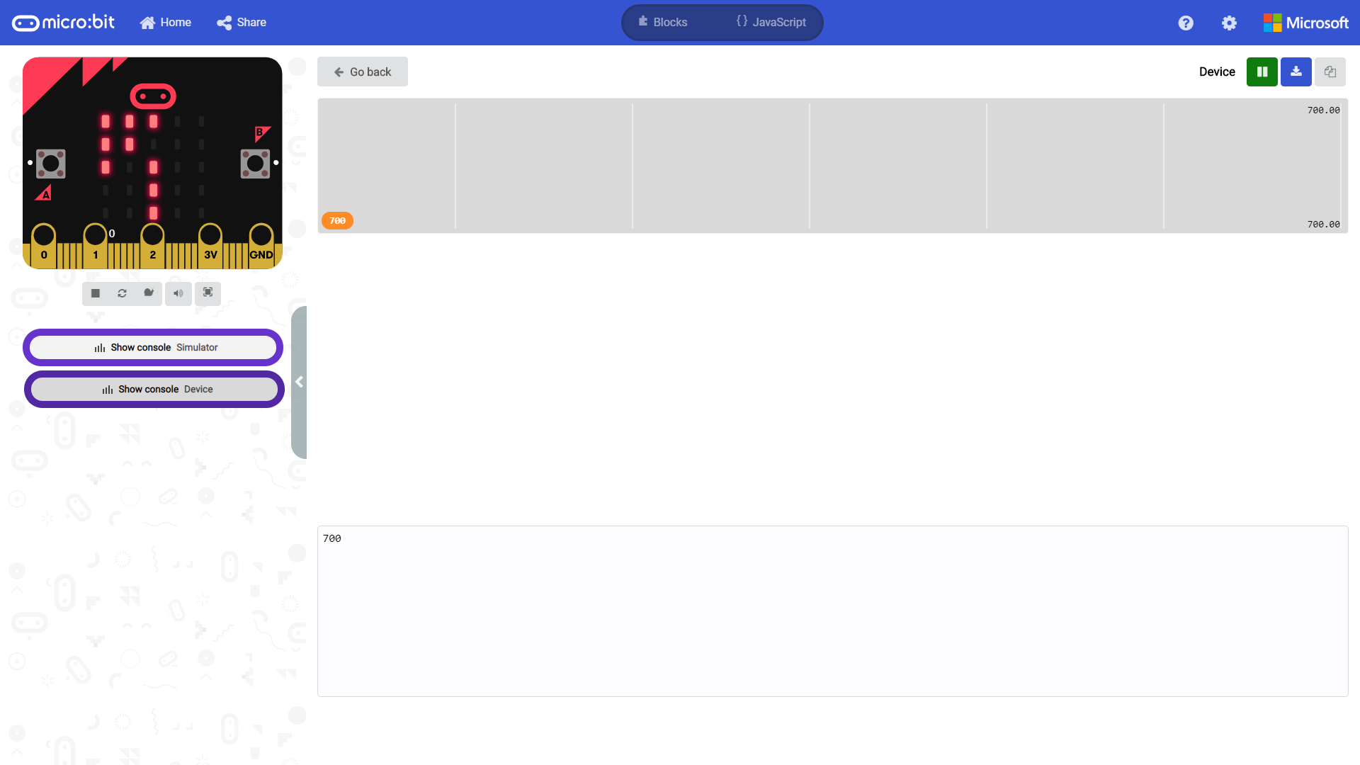
You will notice that the data will start jumping around as the line following sensor on P1 reads the surface. Below is a snapshot of the line following sensor on a white table. The surface that the sensor was reading was not perfectly white and caused the sensor readings to jump around ~693 to ~721. You may see a different output depending on the line following sensor, surface, and distance between the sensor and surface.
To better understand what is going on when the line following sensor sees a dark black line, we'll place different surfaces under the sensor. We'll use the following three surfaces to illustrate what is happening in the graph:
- white table
- brown cardboard
- black electrical tape
 |
 |
 |
| White Table under P1 | Brown Cardboard under P1 | Black Electrical Tape under P1 |
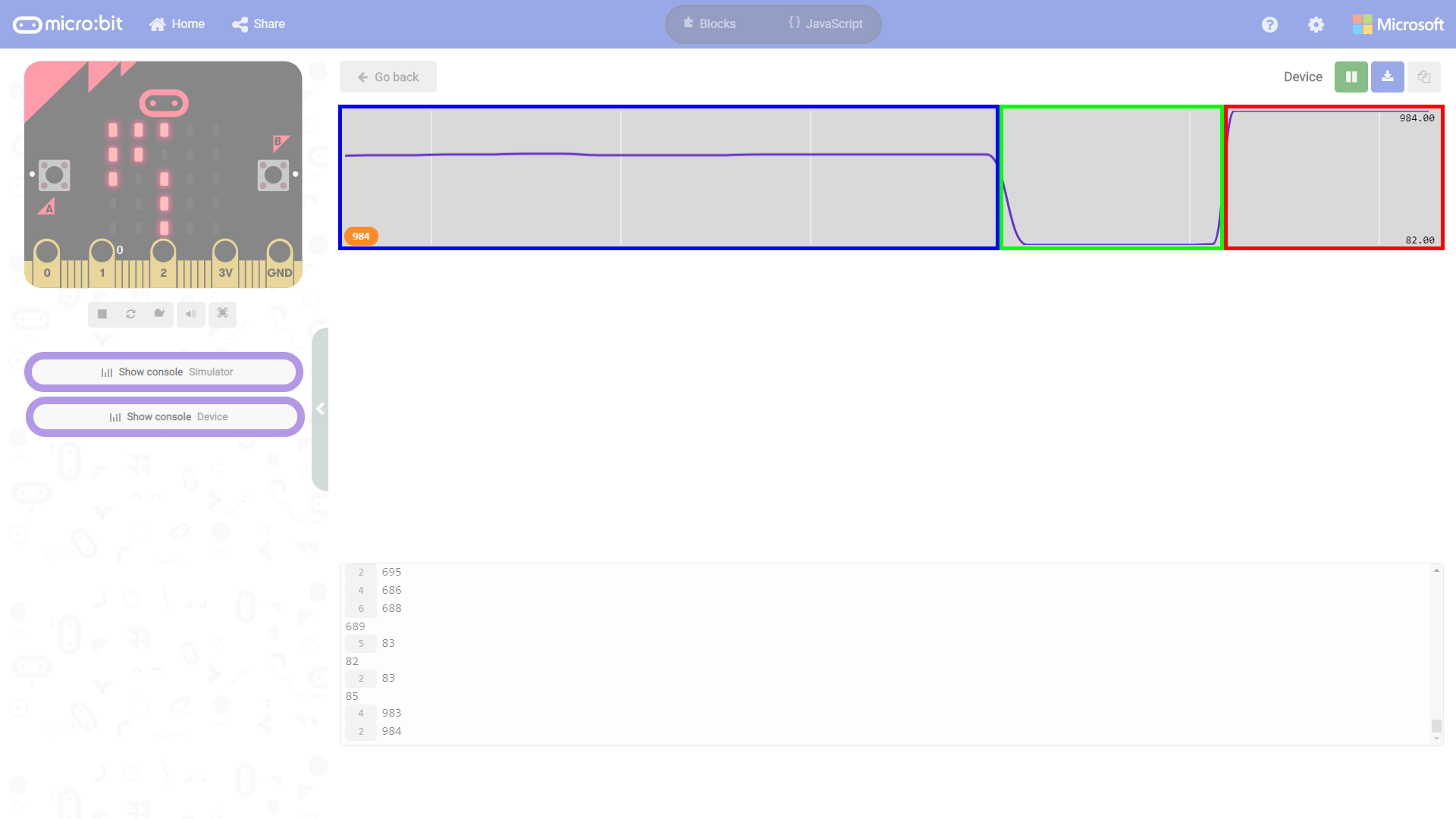
The MakeCode serial plotter automatically zooms in/out so it may be hard to view the data at first. Placing a different surface under the sensor with the micro:bot staying still makes it easy to see the output once the console zooms out. Here's the raw output after placing the table, cardboard, and electrical tape under the sensor for a few seconds.

Let's look at the same graph but highlighted for the different surfaces. The output highlighted in blue was the surface that we initially read (which was ~693 to ~721). The small changes in the readings seem insignificant when comparing the output to other surfaces. Placing a small piece of brown cardboard under the sensor will cause the sensor readings to drop a certain range. The surface of the cardboard was a bit higher than the surface of the table. In this case, it was about ~82 to ~85 as highlighted in green. Moving the sensor over a dark black line will cause the sensor readings to jump to a certain range again. In this case, the values were around ~943 to ~983 as highlighted in red. Feel free to take some notes down on paper to remember what your range is for different surfaces.
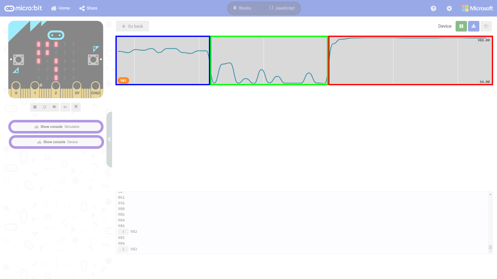
If you turn on the motor and have the micro:bot take a few steps across each surface, you'll notice that the output starts becoming noisy instead of being a steady output. This is due to the small differences across the surface and the IR light being reflected back while the micro:bot is moving. There also might be some noise coming from the batteries whenever the motors pull power and sunlight coming from the windows.
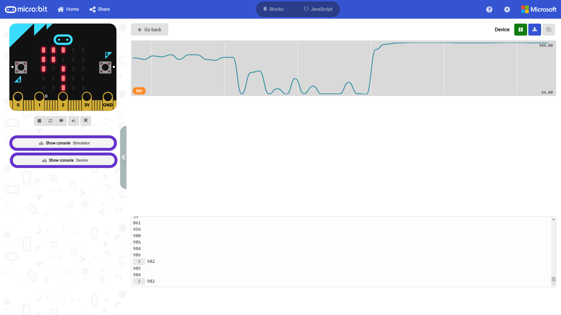
If we inspect the output when the sensor is over the white table (highlighted in blue), the readings jump around ~632 to ~813. This is a bit bigger than what we initially read. If we inspect the output when the sensor is over the brown cardboard surface (highlighted in green), the readings jump around between ~60 to ~650. This is bigger than what we initially read. One reason for this is that the brown cardboard is not uniform throughout the material. Additionally, the distance between the line following sensor and cardboard became the same as when it was driving over the white table. If we inspect the output when the sensor is over black electrical tape (highlighted in red), the readings jump around ~932 to ~988. This is a bit bigger than what we initially read with the white table but not as big as the brown cardboard surface.
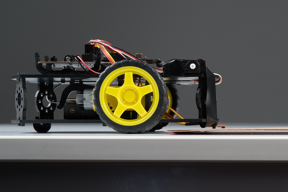 |
 |
| Distance Between Line Following Sensor and Surface Too Close | Optimum Distance Between Line Following Sensor and Surface |
Now that we understand the output, we can head back into the code to adjust it as necessary where it says black_line - 100 to distinguish a light surface (white table or brown cardboard) from a dark surface (i.e. black electrical tape). Since we know that the values for a dark black line will be anything above ~932, we take that baseline value connected to P1 and subtract it by 100. Subtracting it by a value of 100 gives the line following sensor some tolerances in case there is an error in reading a black line. As a result, anything above ~832 will be recognized as a black line. The image below highlights the area in red where it is black_line - 100. If the current reading is above the boundary (indicated by the red line), the micro:bot will recognize it as the black electrical tape. Keep in mind that the analog sensor is not able to go higher than 1023, so anything between ~823 to ~1023 will be recognized as a dark line and does not need to be included in the code. Depending on your surfaces, you may need to adjust the value as necessary to change the sensitivity.
Roaming micro:bot
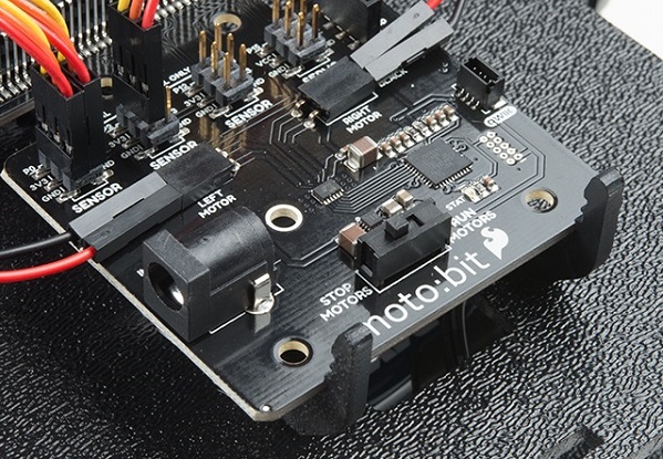
Once your code is loaded find a light surface, preferably white and add a line of black electrical tape to the surface. For simplicity, let's make the width of the line between 1.5 inches and 2.0 inches. Continue adding black electrical tape until you make a square. In fact, if you have a large enough space you can create a 3 foot square you will be perfect! Place the center line following sensor connected to P1 on the black line. Then press the RESET button on your micro:bit. The micro:bot will remember what a black line looks like. Make sure to change the motor switch from "STOP MOTORS" to "RUN MOTORS." If you ever need to re-calibrate the sensor while the code is running, simply place the line following sensor connected to P1 over the dark black line and press the A button.
 |
 |
| Switch Flipped to STOP MOTORS | Switch Flipped to RUN MOTORS |
The micro:bot will try to move away from the black line by backing up and turn to the left a bit. Your robot will attempt to drive forward until the black tape is directly under the center line sensors. When that happens your robot will stop, reverse, pivot to the left a bit, and try to drive forward again before hitting a line once more. If it works correctly and your robot is within the black square line, your robot should stay inside of the box forever!
show LEDs code blocks, adjusting the speed of the motors, and tweaking the pause blocks to see if you can get the micro:bot to move faster in the square. Or maybe try to use what you now know to build a maze for your robot to solve on its own! Better yet, try adjusting the logic used in the if statements to have the micro:bot driving on a black surface and contained within a white line.
Troubleshooting
Moto:Bit blocks not showing up - Make sure you have a network connection and you have added the package to your makeCode environment.
Micro:Bit Not Showing Up On My Machine - Try unplugging the USB cable and plugging it back in. Also, be sure that you have the cable inserted all the way into your micro:bit
Robot Not Moving - Make sure your motors are hooked up correctly in the motor ports and your motor power switch is set to “RUN Motors”, the battery pack is plugged in, and you have fresh batteries.
Robot Not Driving Forward - If your motors are hooked up correctly and we have inverted both motors in the code, try hitting the reset button on the micro:bit. This can happen after uploading when initially powering the micro:bit up.
Moving in Reverse?! - There are two options if you notice the micro:bot moving in the wrong direction. As explained above, you can flip the wiring of your motors or use the
set ____ motor invert to ____block in youron startblock to change what is forward vs. reverse.Robot Drives Over the Black Line - Your motors may still be running as the micro:bit is updating the LEDs pausing, or sending serial data to the USB. Make sure to have the micro:bot drive forward slowly (but not to slow where the motors will not move) before taking an additional sensor reading. You can also try to adjust the values or remove the blocks of code used for debugging. If the micro:bot drives to fast, it will not be able to see the width of the black line. The width of the line may be too small or the material for the black line might not be dark enough for the micro:bot to see. Try increasing the width of the black line or changing the material (i.e. besides black electrical tape, try using a darker paint, marker, pencil, etc.) used for the black line.
Robot Doesn't Detect Line - If changing the width of your line doesn't help, remember line sensor calibration settings can be very sensitive depending on your environment. Press the A button to calibrate when the robot is on the
black_lineor change the value being subtracted from theblack_line.