MicroMod mikroBUS™ Carrier Board Hookup Guide
Introduction
Advanced Product: Novice users, may find the amount information contained in this tutorial somewhat daunting. This board is relatively complex and involves compatibility with three separate ecosystems and can be utilize two different development environments.
- For beginners, who have never programmed; we highly recommend that these users begin with a simpler microcontroller learning kit; such as the SparkFun Inventor's Kit (SIK). The kit includes a simpler microcontroller development board like the Arduino Uno or SparkFun RedBoard.
- For slightly more advanced users who aren't familiar with the MicroMod ecosystem, but are at least familiar with programming; we recommend that these users begin with a basic MicroMod board combination. The MicroMod Qwiic carrier board and SAMD51 processor board are a great introductory board combination from the MicroMod product line.
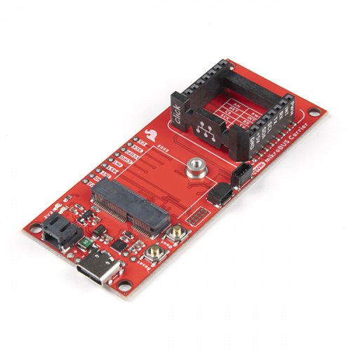
Introducing the our most versatile development board, the MicroMod mikroBUS™ Carrier Board! This new board takes advantage of the MicroMod, Qwiic, and the mikroBUS™ ecosystems and allows users to take advantage of the growing number of 7 MicroMod processor boards, 83 Qwiic (add-on) boards, and 1079 available Click boards™ (as of September 2021), which equates to +51M different board combinations.
The mikroBUS™ standard was developed by MikroElektronika. Similar to our Qwiic and MicroMod interfaces, mikroBUS™ provides a standardized connection for add-on Click boards™ to be hooked up to a microcontroller based development board.
For more details, check out their blog post on the 1000th Click board™ and the origins of the mikroBUS™ standard and mikroBUS™ standard specifications.
Required Materials
To get started, users will need a few of items listed below. (You may already have a some of these items; read through the guide and modify your cart accordingly.)
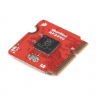
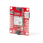
MicroMod Processor Board
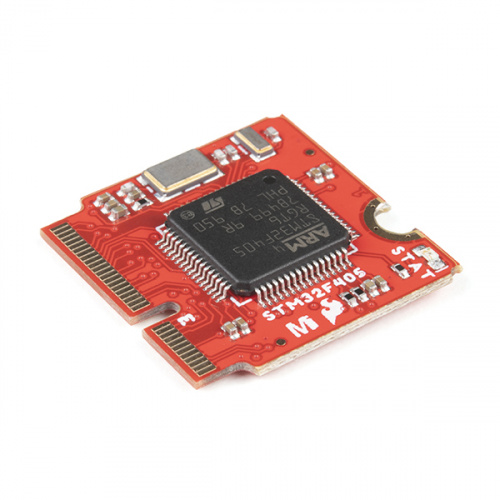
Like other MicroMod Carrier Boards, a Processor Board is required for the product to operate. Users will need a Processor Board (of their choice) to attach to the MicroMod M.2 connector; since, one is not included with this product. Below, are few options; however, we recommend the STM32 processor board. Currently, it is the only processor board supported by Necto Studio and the Arduino IDE.
Required Hardware
A Phillips screw driver is necessary to attach the Processor board to the Carrier Board.

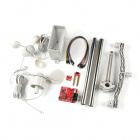
JTAG Programming
To program the STM32 processor board (recommended) through Necto Studio (preferred), users will need a JTAG programmer. Below are programmers that are compatible with the Necto Studio software.
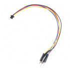
Users will also need some soldering equipment and a JTAG header to connect the programmer to the board. Additionally, with the (recommended) programmers, an adapter is needed to convert the .1" (100 mil) header spacing of the programmer's cable to the .05" (50 mil) header spacing of the JTAG pins on the MicroMod mikroBUS™ carrier board.


USB Programming
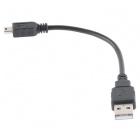
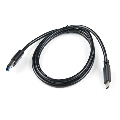
To program a MicroMod processor through the Arduino IDE (not the preferred method), a USB-C cable is needed to connect the Carrier Board to a computer.

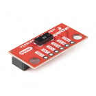
Click Board™
We recommend purchasing a Click board™ to utilize the mikroBUS™ socket. Feel free to choose from any of the available Click boards™ in our catalog. Below are a few options.
Note: If users intend to use Click board™, with code that requires a serial data output, there are no serial pins broken out on the board besides the mikroBUS™ socket. Therefore, it is recommended that users also purchase the MIKROE Terminal Click, a 3.3V serial-to-UART adapter, jumper wires, and corresponding USB cable to access the serial data pins from the mikroBUS™ socket. Below, are a few options from our catalog:
Optional Hardware
To connect Qwiic breakout boards for your MicroMod project, Qwiic cables are required.

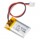
A single-cell Lithium-ion battery can be connected to the Qwiic Carrier Board for portability.


To modify the jumpers, users will need soldering equipment and/or a knife.

Suggested Reading
The MicroMod ecosystem is a unique way to allow users to customize their project to their needs. The Qwiic connect system is a simple method for interfacing with I2C devices. The mikroBUS™ socket is a standardized interface for the MIKROE Click boards™. Click on the banners below for more information on each ecosystem.
For users who aren't familiar with the following concepts, we also recommend reading the following tutorials before continuing.
How to Solder: Through-Hole Soldering
Serial Communication
Serial Peripheral Interface (SPI)
Analog vs. Digital
Processor Interrupts with Arduino
Getting Started with MicroMod
Designing with MicroMod
MicroMod STM32 Processor Hookup Guide
Getting Started with Necto Studio
Installing an Arduino Library
Installing Arduino IDE
Installing Board Definitions in the Arduino IDE
Hardware Overview
Board Dimensions
The MicroMod mikroBUS™ carrier board dimensions are approximately 3.35" x 1.40" with four mounting holes compatible with 4-40 screws or standoffs.
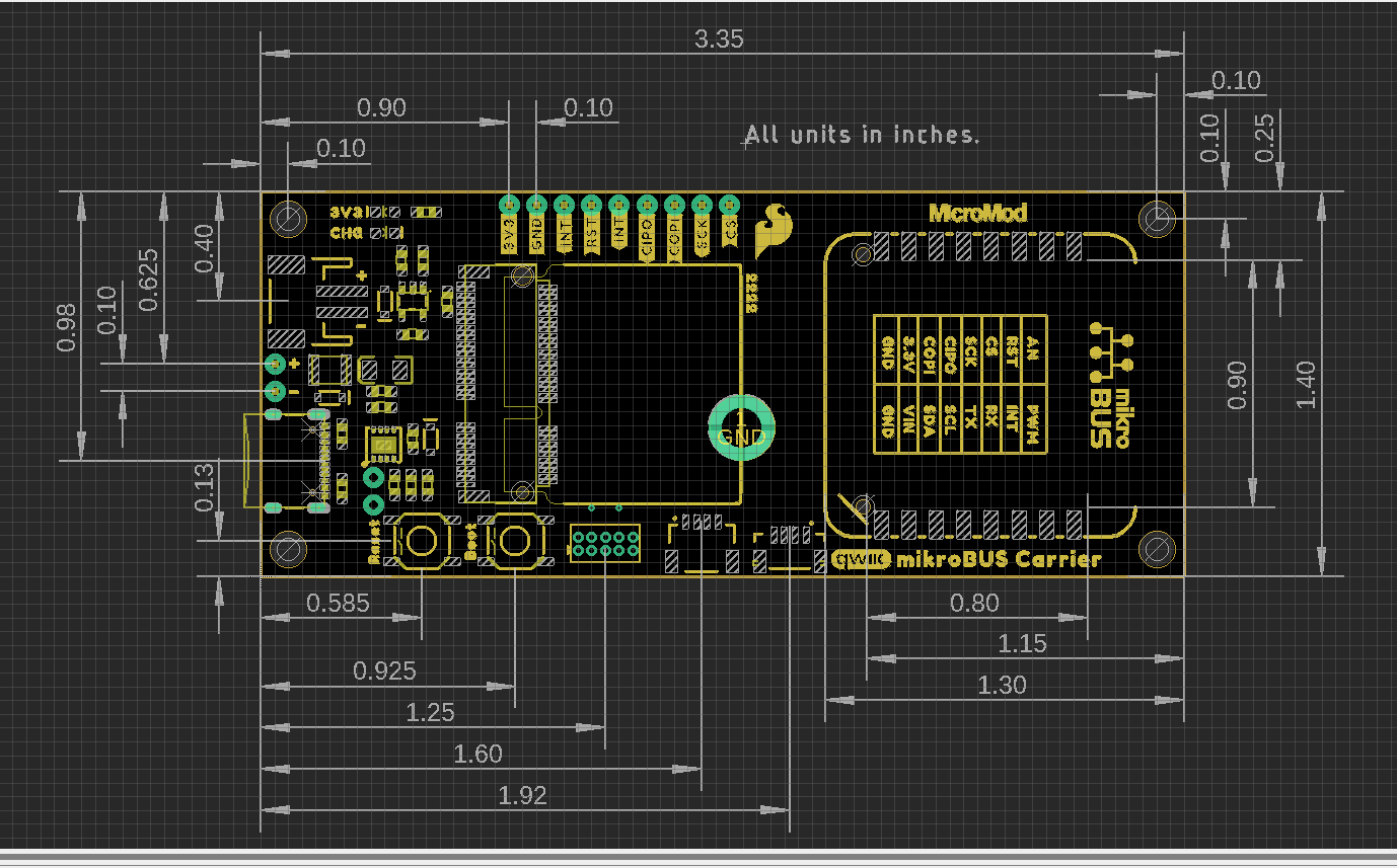
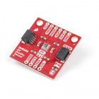
The board also includes a mikroBUS™ socket for MikroElektronika's Click boards™.
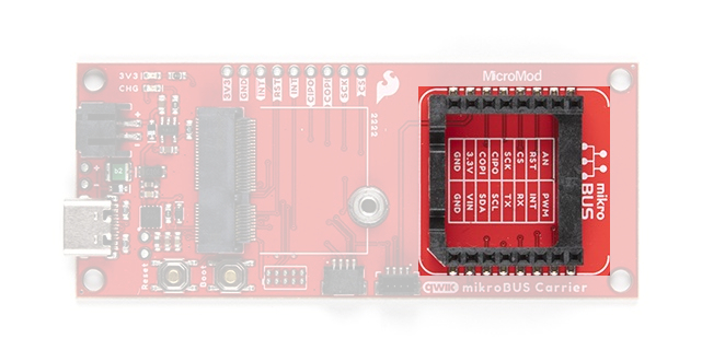
Common Components
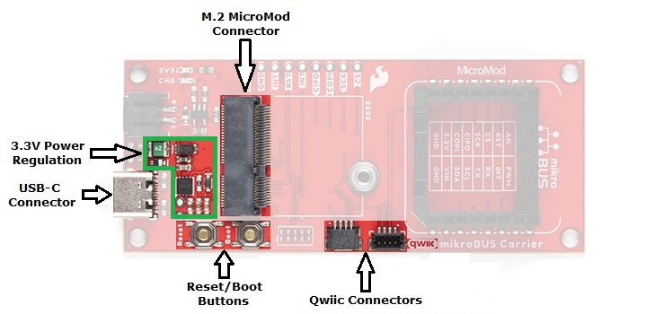
Most SparkFun MicroMod Carrier Boards will have some common components and all MicroMod Carrier Boards will have the keyed M.2 MicroMod connector for a Processor board. The photo and list below outline the common components between the mikroBUS™ carrier board and other MicroMod Carrier Boards.
- M.2 MicroMod Connector - This special keyed M.2 connector lets you install your MicroMod Processor of choice to the mikroBUS Carrier Board.
- USB-C Connector - Connect to your computer to program your processor and provide power to the board.
- 3.3V Regulator - Provides a regulated 3.3V and sources up to 1A.
- Qwiic Connectors - The standard Qwiic connectors to connect other Qwiic devices for your MicroMod project.
- Boot/Reset Buttons - Push buttons to enter boot mode on processors and to reset your MicroMod circuit.
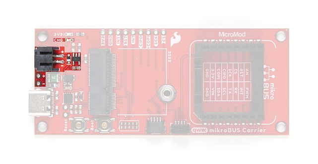
Battery Charger
The board also has a MCP73831 Single-Cell Lithium-Ion/Lithium-Polymer Charge IC so you can charge an attached single-cell LiPo battery. The charge IC receives power from the USB connection and can source up to 450mA to charge an attached battery.
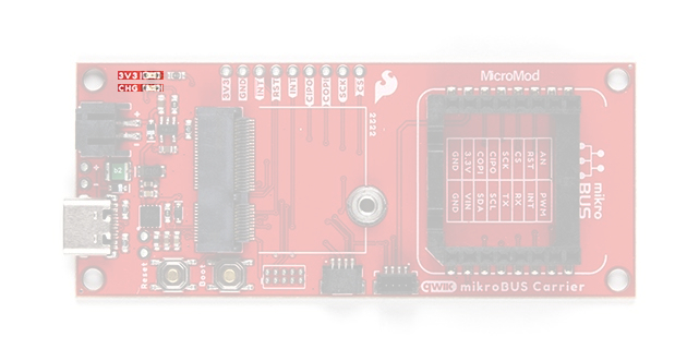
Status LEDs
The carrier board has two status LEDs:
- 3V3 - This LED indicates when 3.3V power is available top the board.
- CHG - This LED indicates the status of the charging circuit operation.
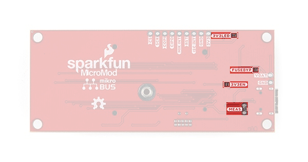
Solder Jumpers
There are four adjustable solder jumpers on the mikroBUS™ carrier board labeled MEAS, BYP, 3.3V_VE and 3.3V. The table below briefly outlines their functionalities:
| Jumper Name/Label | Description | Default State |
|---|---|---|
| Measure/MEAS | Open this jumper to probe the current draw at the 3.3V output of the regulator. For help measuring current, take a look at our How to Use a Multimeter tutorial. | CLOSED |
| Bypass/BYP | The "penny-in-the-fuse" jumper. Bypasses the 6V/2A fuse and nets VIN and V_USB together. Close only if you know what you are doing! | OPEN |
| Voltage Regulator Enable/VE | Voltage regulator control. Close this jumper to control the VREG in low-power applications. | OPEN |
| 3.3V LED Power/3V3 LED | Connects the 3.3V LED to 3.3V via a 1K Ohm resistor. Open to disable the LED. | CLOSED |
MicroMod Pinout
Since this carrier board is designed to work with all of the MicroMod Processors we've included the table below to outline which pins are used so, if you would like, you can compare them to the pinout tables in their respective Hookup Guides.
| AUDIO | UART | GPIO/BUS | I2C | SDIO | SPI | Dedicated |
| Function | Bottom Pin |
Top Pin |
Function | ||||||
|---|---|---|---|---|---|---|---|---|---|
| (Not Connected) | 75 | GND | |||||||
| 3.3V | 74 | 73 | G5 / BUS5 | ||||||
| RTC_3V_BATT | 72 | 71 | G6 / BUS6 | ||||||
| SPI_CS1# | SDIO_DATA3 (I/O) | 70 | 69 | G7 / BUS7 | |||||
| SDIO_DATA2 (I/O) | 68 | 67 | G8 | ||||||
| SDIO_DATA1 (I/O) | 66 | 65 | G9 | ADC_D- | CAM_HSYNC | ||||
| SPI_CIPO1 | SDIO_DATA0 (I/O) | 64 | 63 | G10 | ADC_D+ | CAM_VSYNC | |||
| SPI COPI1 | SDIO_CMD (I/O) | 62 | 61 | SPI_CIPO (I) | |||||
| SPI SCK1 | SDIO_SCK (O) | 60 | 59 | SPI_COPI (O) | LED_DAT | ||||
| AUD_MCLK (O) | 58 | 57 | SPI_SCK (O) | LED_CLK | |||||
| CAM_MCLK | PCM_OUT | I2S_OUT | AUD_OUT | 56 | 55 | SPI_CS# | |||
| CAM_PCLK | PCM_IN | I2S_IN | AUD_IN | 54 | 53 | I2C_SCL1 (I/O) | |||
| PDM_DATA | PCM_SYNC | I2S_WS | AUD_LRCLK | 52 | 51 | I2C_SDA1 (I/O) | |||
| PDM_CLK | PCM_CLK | I2S_SCK | AUD_BCLK | 50 | 49 | BATT_VIN / 3 (I - ADC) (0 to 3.3V) | |||
| G4 / BUS4 | 48 | 47 | PWM1 | ||||||
| G3 / BUS3 | 46 | 45 | GND | ||||||
| G2 / BUS2 | 44 | 43 | CAN_TX | ||||||
| G1 / BUS1 | 42 | 41 | CAN_RX | ||||||
| G0 / BUS0 | 40 | 39 | GND | ||||||
| A1 | 38 | 37 | USBHOST_D- | ||||||
| GND | 36 | 35 | USBHOST_D+ | ||||||
| A0 | 34 | 33 | GND | ||||||
| PWM0 | 32 | 31 | Module Key | ||||||
| Module Key | 30 | 29 | Module Key | ||||||
| Module Key | 28 | 27 | Module Key | ||||||
| Module Key | 26 | 25 | Module Key | ||||||
| Module Key | 24 | 23 | SWDIO | ||||||
| UART_TX2 (O) | 22 | 21 | SWDCK | ||||||
| UART_RX2 (I) | 20 | 19 | UART_RX1 (I) | ||||||
| CAM_TRIG | D1 | 18 | 17 | UART_TX1 (0) | |||||
| I2C_INT# | 16 | 15 | UART_CTS1 (I) | ||||||
| I2C_SCL (I/0) | 14 | 13 | UART_RTS1 (O) | ||||||
| I2C_SDA (I/0) | 12 | 11 | BOOT (I - Open Drain) | ||||||
| D0 | 10 | 9 | USB_VIN | ||||||
| SWO | G11 | 8 | 7 | GND | |||||
| RESET# (I - Open Drain) | 6 | 5 | USB_D- | ||||||
| 3.3V_EN | 4 | 3 | USB_D+ | ||||||
| 3.3V | 2 | 1 | GND | ||||||
| Signal Group | Signal | I/O | Description | Voltage | Power | 3.3V | I | 3.3V Source | 3.3V |
|---|---|---|---|---|
| GND | Return current path | 0V | ||
| USB_VIN | I |
USB VIN compliant to USB 2.0 specification. Connect to pins on Processor Board that require 5V for USB functionality. |
4.8-5.2V | |
| RTC_3V_BATT | I |
3V provided by external coin cell or mini battery. Max draw = 100μA. Connect to pins maintaining an RTC during power loss. Can be left NC. |
3V | |
| 3.3V_EN | O | Controls the carrier board's main voltage regulator. Voltage above 1V will enable 3.3V power path. | 3.3V | |
| BATT_VIN/3 | I |
Carrier board raw voltage over 3. 1/3 resistor divider is implemented on carrier board. Amplify the analog signal as needed for full 0-3.3V range |
3.3V | |
| Reset | Reset | I | Input to processor. Open drain with pullup on processor board. Pulling low resets processor. | 3.3V |
| Boot | I | Input to processor. Open drain with pullup on processor board. Pulling low puts processor into special boot mode. Can be left NC. | 3.3V | |
| USB | USB_D± | I/O | USB Data ±. Differential serial data interface compliant to USB 2.0 specification. If UART is required for programming, USB± must be routed to a USB-to-serial conversion IC on the processor board. | |
| USB Host | USBHOST_D± | I/O | For processors that support USB Host Mode. USB Data±. Differential serial data interface compliant to USB 2.0 specification. Can be left NC. | |
| CAN | CAN_RX | I | CAN Bus receive data. | 3.3V |
| CAN_TX | O | CAN Bus transmit data. | 3.3V | |
| UART | UART_RX1 | I | UART receive data. | 3.3V |
| UART_TX1 | O | UART transmit data. | 3.3V | |
| UART_RTS1 | O | UART request to send. | 3.3V | |
| UART_CTS1 | I | UART clear to send. | 3.3V | |
| UART_RX2 | I | 2nd UART receive data. | 3.3V | |
| UART_TX2 | O | 2nd UART transmit data. | 3.3V | |
| I2C | I2C_SCL | I/O | I2C clock. Open drain with pullup on carrier board. | 3.3V |
| I2C_SDA | I/O | I2C data. Open drain with pullup on carrier board | 3.3V | |
| I2C_INT# | I | Interrupt notification from carrier board to processor. Open drain with pullup on carrier board. Active LOW | 3.3V | |
| I2C_SCL1 | I/O | 2nd I2C clock. Open drain with pullup on carrier board. | 3.3V | |
| I2C_SDA1 | I/O | 2nd I2C data. Open drain with pullup on carrier board. | 3.3V | |
| SPI | SPI_COPI | O | SPI Controller Output/Peripheral Input. | 3.3V |
| SPI_CIPO | I | SPI Controller Input/Peripheral Output. | 3.3V | |
| SPI_SCK | O | SPI Clock. | 3.3V | |
| SPI_CS# | O | SPI Chip Select. Active LOW. Can be routed to GPIO if hardware CS is unused. | 3.3V | |
| SPI/SDIO | SPI_SCK1/SDIO_CLK | O | 2nd SPI Clock. Secondary use is SDIO Clock. | 3.3V |
| SPI_COPI1/SDIO_CMD | I/O | 2nd SPI Controller Output/Peripheral Input. Secondary use is SDIO command interface. | 3.3V | |
| SPI_CIPO1/SDIO_DATA0 | I/O | 2nd SPI Peripheral Input/Controller Output. Secondary use is SDIO data exchange bit 0. | 3.3V | |
| SDIO_DATA1 | I/O | SDIO data exchange bit 1. | 3.3V | |
| SDIO_DATA2 | I/O | SDIO data exchange bit 2. | 3.3V | |
| SPI_CS1/SDIO_DATA3 | I/O | 2nd SPI Chip Select. Secondary use is SDIO data exchange bit 3. | 3.3V | |
| Audio | AUD_MCLK | O | Audio master clock. | 3.3V |
| AUD_OUT/PCM_OUT/I2S_OUT/CAM_MCLK | O | Audio data output. PCM synchronous data output. I2S serial data out. Camera master clock. | 3.3V | |
| AUD_IN/PCM_IN/I2S_IN/CAM_PCLK | I | Audio data input. PCM syncrhonous data input. I2S serial data in. Camera periphperal clock. | 3.3V | |
| AUD_LRCLK/PCM_SYNC/I2S_WS/PDM_DATA | I/O | Audio left/right clock. PCM syncrhonous data SYNC. I2S word select. PDM data. | 3.3V | |
| AUD_BCLK/PCM_CLK/I2S_CLK/PDM_CLK | O | Audio bit clock. PCM clock. I2S continuous serial clock. PDM clock. | 3.3V | |
| SWD | SWDIO | I/O | Serial Wire Debug I/O. Connect if processor board supports SWD. Can be left NC. | 3.3V |
| SWDCK | I | Serial Wire Debug clock. Connect if processor board supports SWD. Can be left NC. | 3.3V | |
| ADC | A0 | I | Analog to digital converter 0. Amplify the analog signal as needed to enable full 0-3.3V range. | 3.3V |
| A1 | I | Analog to digital converter 1. Amplify the analog signal as needed to enable full 0-3.3V range. | 3.3V | |
| PWM | PWM0 | O | Pulse width modulated output 0. | 3.3V |
| PWM1 | O | Pulse width modulated output 1. | 3.3V | |
| Digital | D0 | I/O | General digital input/output pin. | 3.3V |
| D1/CAM_TRIG | I/O | General digital input/output pin. Camera trigger. | 3.3V | |
| General/Bus | G0/BUS0 | I/O | General purpose pins. Any unused processor pins should be assigned to Gx with ADC + PWM capable pins given priority (0, 1, 2, etc.) positions. The intent is to guarantee PWM, ADC and Digital Pin functionality on respective ADC/PWM/Digital pins. Gx pins do not guarantee ADC/PWM function. Alternative use is pins can support a fast read/write 8-bit or 4-bit wide bus. | 3.3V |
| G1/BUS1 | I/O | 3.3V | ||
| G2/BUS2 | I/O | 3.3V | ||
| G3/BUS3 | I/O | 3.3V | ||
| G4/BUS4 | I/O | 3.3V | ||
| G5/BUS5 | I/O | 3.3V | ||
| G6/BUS6 | I/O | 3.3V | ||
| G7/BUS7 | I/O | 3.3V | ||
| G8 | I/O | General purpose pin | 3.3V | |
| G9/ADC_D-/CAM_HSYNC | I/O | Differential ADC input if available. Camera horizontal sync. | 3.3V | |
| G10/ADC_D+/CAM_VSYNC | I/O | Differential ADC input if available. Camera vertical sync. | 3.3V | |
| G11/SWO | I/O | General purpose pin. Serial Wire Output | 3.3V |
| M.2 Pin# | MicroMod Pin Name | Board Connections | Description |
|---|---|---|---|
| 1 | GND |
GND
mikroBUS™ Socket - GND |
Ground plane |
| 2 | 3.3V |
3.3V
mikroBUS™ Socket - +3.3V |
Regulated 3.3V via USB-C |
| 3 | USB_D+ | -- | USB D+ connection for Processor Board |
| 4 | 3.3V_EN | -- | Voltage regulator enable input |
| 5 | USB_D- | -- | USB D- connection for Processor Board |
| 6 | RESET | RESET Button |
Connected to RESET Button
Reset is active LOW |
| 9 | USB_VIN | mikroBUS™ Socket - +5V | Input voltage from USB |
| 10 | D0 |
D0
mikroBUS™ Socket - INT |
Digital I/O pin |
| 11 | BOOT | BOOT Button |
Connected to BOOT Button
Boot is active LOW |
| 12 | I2C_SDA |
SDA
Qwiic Connector - SDA mikroBUS™ Socket - SDA |
I2C data signal for Qwiic devices |
| 14 | I2C_SCL |
SCL
Qwiic Connector - SCL mikroBUS™ Socket - SCL |
I2C clock signal for Qwiic devices |
| 16 | I2C_INT | INT | I2C interrupt pin |
| 17 | UART_TX1 | mikroBUS™ Socket - TX | UART transmit data pin |
| 18 | D1 |
D1
mikroBUS™ Socket - RST |
Digital I/O pin |
| 19 | UART_RX1 | mikroBUS™ Socket - RX | UART receive data pin |
| 32 | PWM0 | mikroBUS™ Socket - PWM | PWM output pin |
| 34 | A0 | mikroBUS™ Socket - AN | ADC input pin |
| 55 | SPI_CS |
CS
mikroBUS™ Socket - CS |
SPI Chip Select |
| 57 | SPI_SCK |
SCK
mikroBUS™ Socket - SCK |
SPI Clock signal |
| 59 | SPI_COPI |
COPI
mikroBUS™ Socket - MOSI |
SPI Controller Out/Peripheral In signal |
| 61 | SPI_CIPO |
CIPO
mikroBUS™ Socket - MISO |
SPI Controller In/Peripheral Out signal |
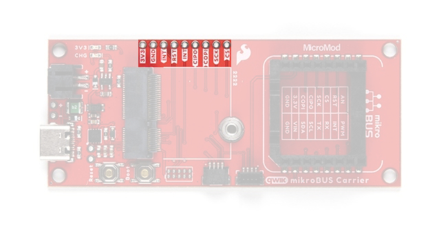
Breakout Pins
The mikroBUS™ carrier board features a 3.3V, a ground, seven I/O breakout pins. The functionality of these pins are detailed in the table above.
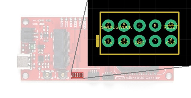
JTAG Pins
The mikroBUS™ carrier board includes JTAG PTH pins for a JTAG header, to be used with one of the recommended MikroElektronica mikroProg programmers. The JTAG pins breakout the SWD (software debug) pins to the MicroMod processor board.
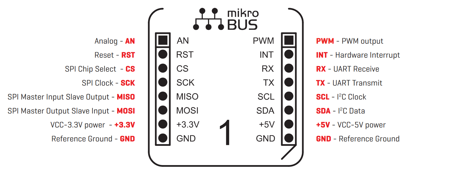
mikroBUS™ Socket
The most significant feature of this board, is the addition of the mikroBUS™ socket, which provides a drop-in interface for MikroElektronka's ecosystem of Click boards™ (over 1079 as of September 2021).
The mikroBUS™ socket comprises a pair of 8-pin female headers with a standardized pin configuration. The pins consists of three groups of communications pins (SPI, UART and I2C), six additional pins (PWM, Interrupt, Analog input, Reset and Chip select), and two power groups (3.3V and 5V).
|
mikroBUS™ Socket
Pin Name |
Carrier Board's
Processor Pin |
mikroBUS™ Socket
I/O Direction |
Description |
|---|---|---|---|
| 5V | USB_VIN | Input | Power supply: 4.75~5.5V |
| 3.3V | 3.3V | Input | Power supply: 3.3V |
| GND | - | - | Ground |
| SCK | SCK (57) | Input | SPI - Clock signal |
| CIPO | CIPO (59) | Output | SPI - Data from mikroBUS™ socket |
| COPI | COPI (61) | Input | SPI - Data to mikroBUS™ socket |
| CS | CS0 (55) | Input | SPI - Chip select for mikroBUS™ socket |
| SCL | SCL (14) | Input/Output | I2C - Clock signal |
| SDA | SDA (12) | Input/Output | I2C - Data signal to/from mikroBUS™ socket |
| TX | TX1 (17) | Input | TX - Serial data to mikroBUS™ socket |
| RX | RX1 (19) | Output | RX - Serial data from mikroBUS™ socket |
| RST | D1 (18) | Input | Reset signal to mikroBUS™ socket |
| INT | D0 (10) | Output | Interrupt trigger from mikroBUS™ socket |
| AN | A0 (34) | Output | Analog output from mikroBUS™ socket |
| PWM | PWM0 (32) | Input | PWM signal to mikroBUS™ socket |
*For more information about the mikroBUS™ socket, click here for the mikroBUS™ standard specifications.
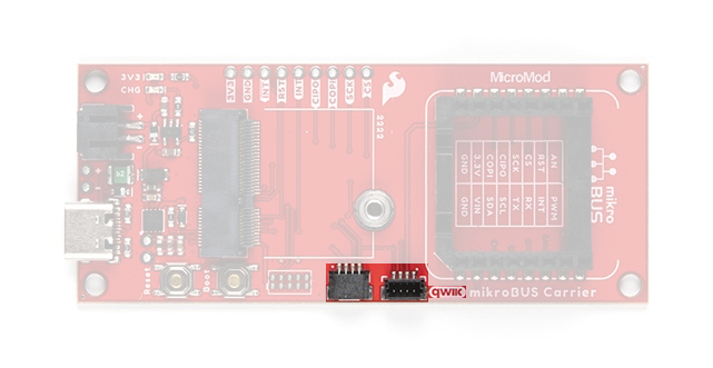
Qwiic Connector
The Qwiic connectors are provided for users to seamlessly integrate with SparkFun's Qwiic Ecosystem.
What is Qwiic?
The Qwiic system is intended a quick, hassle-free cabling/connector system for I2C devices. Qwiic is actually a play on words between "quick" and I2C or "iic".
Features of the Qwiic System
Keep your soldering iron at bay.
Cables plug easily between boards making quick work of setting up a new prototype. We currently offer three different lengths of Qwiic cables as well as a breadboard friendly cable to connect any Qwiic enabled board to anything else. Initially you may need to solder headers onto the shield to connect your platform to the Qwiic system but once that’s done it’s plug and go!

Qwiic cables connected to Spectral Sensor Breakout
Minimize your mistakes.
How many times have you swapped the SDA and SCL wires on your breadboard hoping the sensor will start working? The Qwiic connector is polarized so you know you’ll have it wired correctly, every time, from the start.
The PCB connector is part number SM04B-SRSS (Datasheet) or equivalent. The mating connector used on cables is part number SHR04V-S-B or equivalent. This is a common and low cost connector.

1mm pitch, 4-pin JST connector
Expand with ease.
It’s time to leverage the power of the I2C bus! Most Qwiic boards will have two or more connectors on them allowing multiple devices to be connected.

Hadware Assembly
For those unfamiliar with the MicroMod ecosystem, be sure to review the Getting Started with MicroMod guide.
Getting Started with MicroMod
October 21, 2020
MicroMod Processor Board
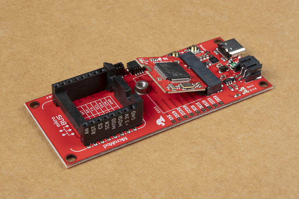
To get started users will need a compatible processor board. Insert the MicroMod processor board into the M.2 socket for the processor board at an angle, with its edge connector aligned to the matching slots.
When inserted properly, the processor board will rest at an angle:
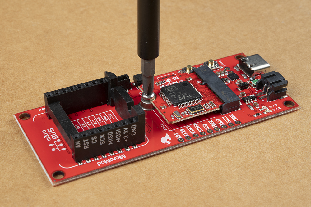
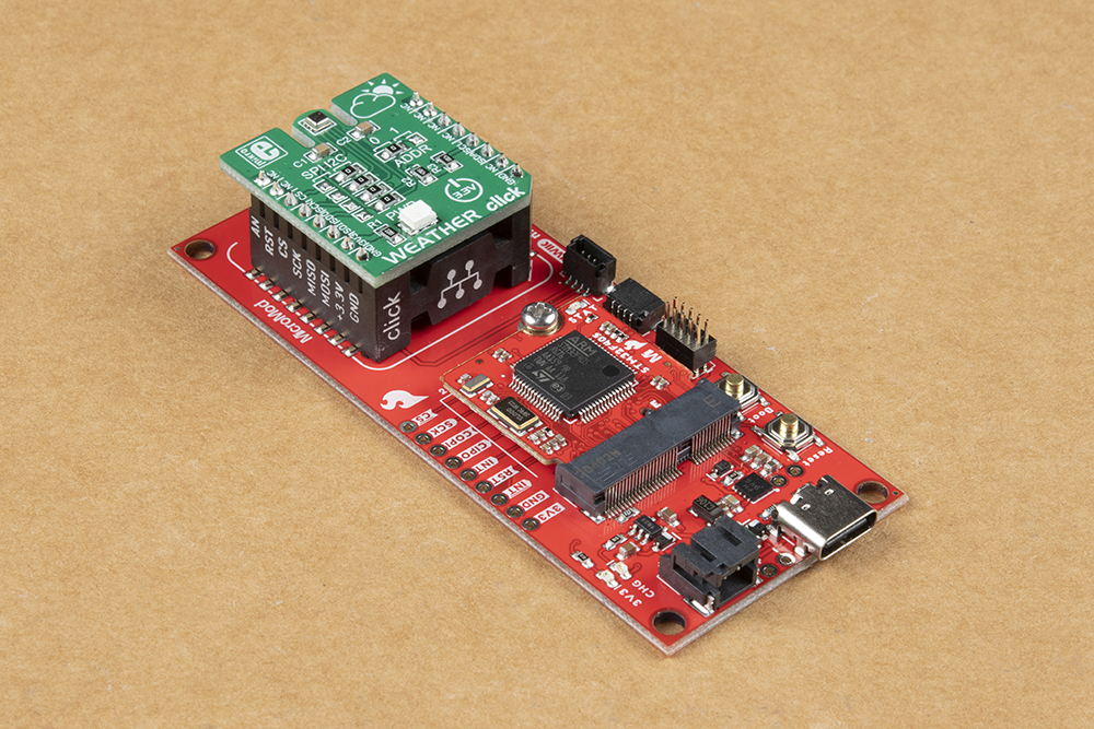
To secure the processor board, gently hold down on the board and attach the M.2 screw with a Phillip's head (PH0 or PH1) screw driver. Below, is an example of an assembled MicroMod system:
JTAG Programming (preferred)
To program the processor board on the MicroMod mikroBUS™ carrier board, users will need a JTAG adapter to convert the .1" (100 mil) header spacing on the programmer cable to the .05" (50 mil) header spacing of the JTAG pins on the MicroMod mikroBUS™ carrier board. Additionally, users will need to solder on a compatible JTAG header to their board.

Programming the MicroMod mikroBUS™ carrier board through the JTAG pins. (Click to enlarge)
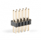
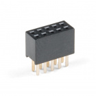
JTAG Header
With the preferred programming method, Necto Studio, users will program the processor board on the MicroMod mikroBUS™ carrier board through the JTAG pins. Therefore, users will need to solder on a JTAG header for the programmer to connect to.

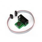
JTAG Adapter
With the recommended programmer, users will need an adapter to convert the .1" (100 mil) header spacing on the programmer cable to the .05" (50 mil) header spacing of the pins on board, .
Note: Users should verify that the pinout for the programmer and adapter match up to the corresponding pins of the MicroMod mikroBUS™ carrier board to avoid damaging the MCU of the processor board. Additionally, preventative measures should be taken if there is a risk that the pins from the adapter could contact the processor board.
The JTAG adatpter with pins exposed over the processor board. (Click to enlarge)

Tape used to prevent shorts on the processor board. (Click to enlarge)
USB Programming (not preferred)
A processor board utilized on the MicroMod mikroBUS™ carrier board, can also be connect to a computer with a USB-C cable and programmed with the Arduino IDE. Depending on the processor board, users may need to install drivers (if they have not done so already).
Note: Make sure that the correct board definitions are installed in the Arduino IDE, for the selected processor board. For help installing board definitions, use the MicroMod processor boards landing page and review the associated hookup guide for that hardware.
Installing Board Definitions in the Arduino IDE
September 9, 2020
To upload a sketch to the STM32 processor board (recommended), users will need to:
- Connect a USB-C cable between the board and the computer
- Hold down the
BOOTbutton - Toggle the
RESETbutton - Hit the upload button in the Arduino IDE, to program the sketch
- Make sure to use the correct setting in the Tools menu for the processor board
- Once the upload process has completed in the Arduino IDE, the
BOOTbutton can be released
Battery
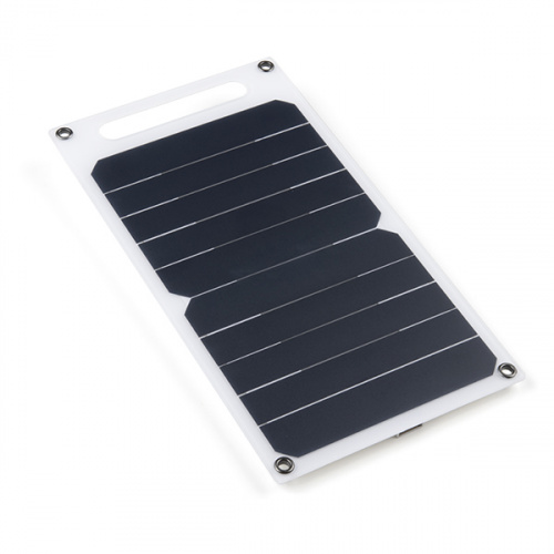
For remote applications, the MicroMod mikroBUS™ carrier board can be powered through its 2-pin JST battery connector. Additionally, users may be interested in utilizing a solar panel and USB-C cable to recharge their battery.
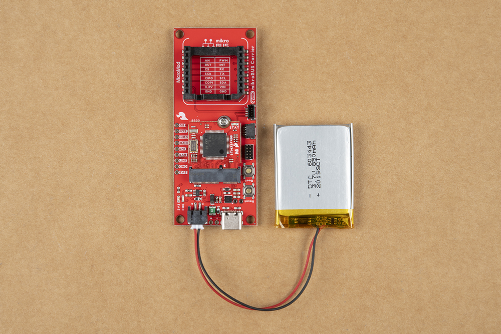
The MicroMod mikroBUS™ carrier board with a battery attached. (Click to enlarge)
Note: DO NOT remove batteries by pulling on their wires. Instead, it is recommended that pair of dikes (i.e. diagonal wire cutters), pliers, or tweezers be used to pull on the JST connector housing, to avoid damaging the battery wiring.
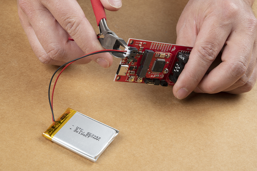
Using a pair of dikes to disconnect a battery. (Click to enlarge)
mikroBUS™ Socket
The MicroMod mikroBUS™ carrier board has a mikroBUS™ Socket, where a Click board™ can be inserted.
Note: To remove a Click board™, slowly and carefully wiggle it out of the mikroBUS™ socket to avoid bending the header pins on their Click board™.
The header also allows users to connect jumper wires to devices that may not have the mikroBUS™ pin layout to interface with.

Serial Data Output
Note: Some of the examples for the Click board™ libraries in Necto Studio, utilize a serial data output to verify functionality. In order to access the serial data output from the mikroBUS™ socket, users can use a Terminal Click Board™, serial-to-UART adapter, and jumper wires.
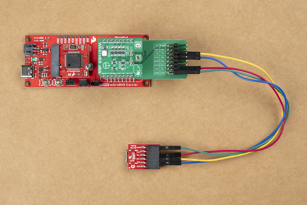
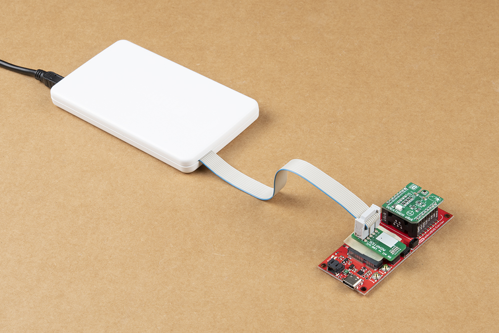
Weather and Terminal Click boards™ inserted into the mikroBUS™ socket of the MicroMod mikroBUS™ carrier board and connected to a serial-to-UART adapter. (Click to enlarge)
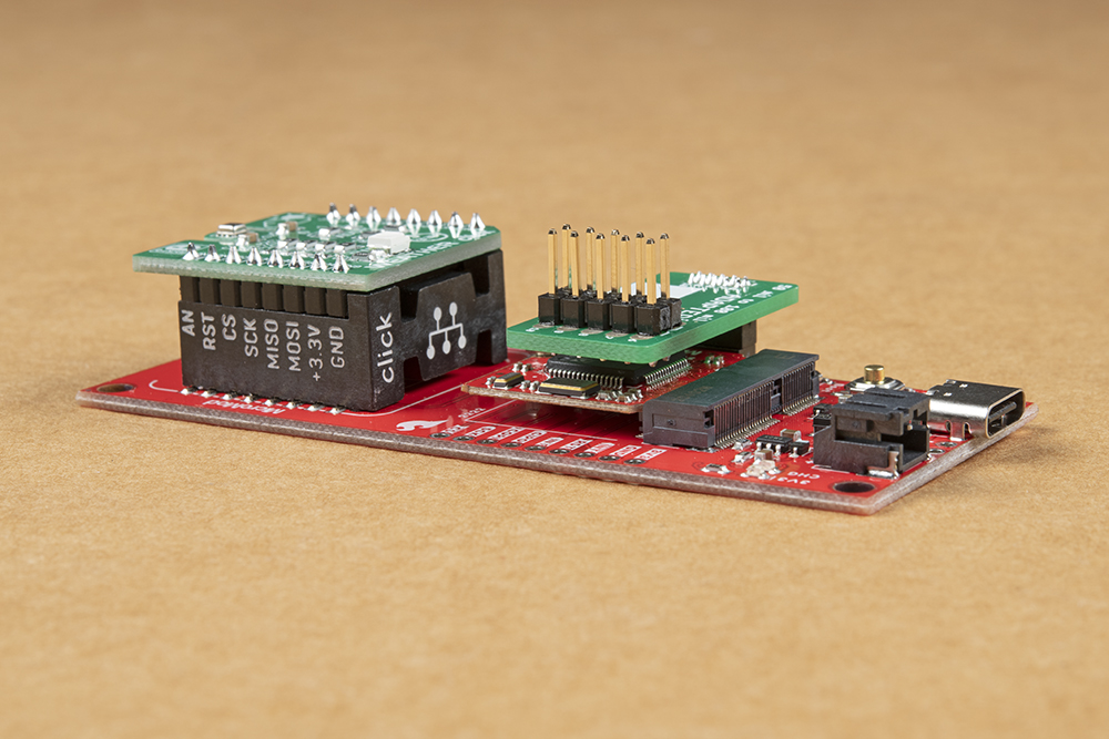
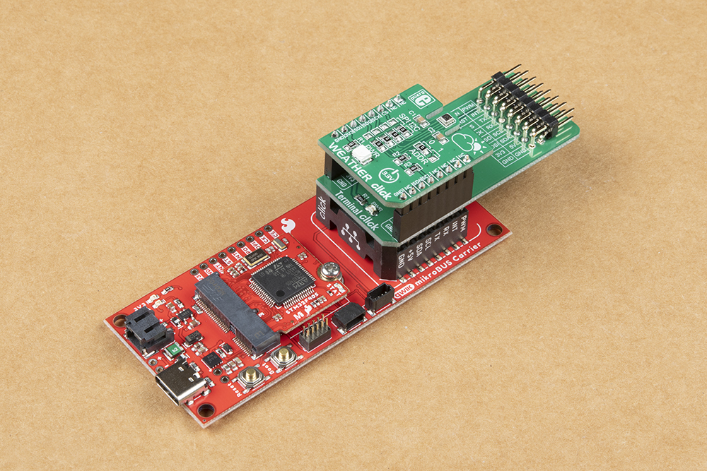
To breakout the pins of the mikroBUS socket™, a Terminal Click board™ can be stacked between a Click board™ and the mikroBUS socket™.
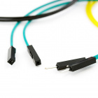
Once the serial pins have been broken out with the Terminal Click board™, users can access the serial pins with a serial-to-UART adapter and some jumper wire. The pin connections are summarized in the table below and illustrated in the following images.
| Terminal Click™ | Serial Breakout | Description |
|---|---|---|
RX |
RXI |
Serial data output from Click board™ to MCU |
TX |
TXO |
Serial data output from MCU to Click board™ |
3.3V |
VCC |
Power input to mikroBUS socket™ |
GND |
GND |
Ground |
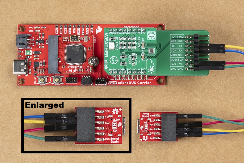
Top view of jumper wire connections. (Click to enlarge)
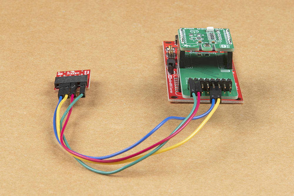
Front view of the jumper wire connections. (Click to enlarge)
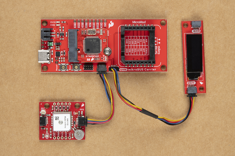
Qwiic Devices
To connect Qwiic devices to the carrier board, users will need Qwiic cables; most of these devices can also be daisy chained together. For more information, check out our Qwiic ecosystem page.
Software Overview
Necto Studio
Necto Studio is a productive cross-platform integrated developing environment provided by MikroElektronika and is available on Windows, Linux, and macOS. It includes C compilers, mikroSDK 2.0, package manager, and USB or WiFi Debugger capabilities with flexible licensing options. The development environment features intelligent code completion, auto-close brackets, and drag and drop visual elements.
Users can find their favorite Click Board library and working example through the Package Manager. Users will also be notified about new versions of installed packages, and easily update in one click.
MikroElektronika even provides first-time users with the longest time trial on the market - Get fully unlocked, feature-rich NECTO for three months, and explore it to the most delicate details before purchase!
For more information about NECTO Studio, please visit the product page.
mikroSDK
mikroSDK 2.0 makes application code portable and reusable on many different platforms and architectures, with virtually no code changes. It is a collection of open-source software libraries with unified API and software development tools. Everything you need to start developing, and prototyping cross-platform embedded applications, including Click board™ applications and GUIs for embedded devices.
mikroSDK 2.0 is open-source, and it’s natively supported in NECTO Studio. The video below, is a brief overview of how to use the mikroSDK:
Additional Resources:
For more details on Necto Studio, check out our getting started guide below:
Getting Started with Necto Studio
March 4, 2022
- When creating a hardware setup, users will want to select:
- mikroC AI for ARM compiler
- mikroSDK (latest)
- MicroMod Carrier Board
- STM32F405RG-Tx (should be only option)
- No display
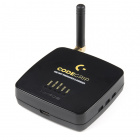
- CODEGRIP Programmer (recommended)
- To be able to debug and program the MCU from Necto Studio, users will want to configure the following target option parameters:
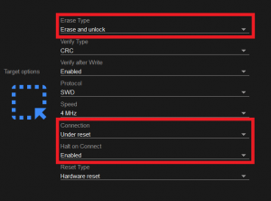 Target options for the CODEGRIP programmer in Necto Studio. (Click to enlarge)
 - Erase Type:
Erase and unlock - Connection:
Under reset - Hold on Connect:
Enabled
- To be able to debug and program the MCU from Necto Studio, users will want to configure the following target option parameters:
- For more details, check out the Setups section of the Necto Studio getting started guide.
- For the CODEGRIP programmer (recommended), users will need to link with the programmer and configure the programming target in the CODEGRIP Suite:
- MCU:
STM32F405RG - Protocol:
SWD - Connection:
Under reset - Halt on Connect:
Enabled - For more details, check out the Programmer Configuration section of the Necto Studio getting started guide.
- MCU:
Arduino IDE
While not the preferred method for programming their board, users can use the Arduino IDE to upload sketches to the MicroMod mikroBUS™ carrier board. We recommend that users select a Click board™ with a supporting Arduino library for their processor board. Below, are a few tips to get users started.
Getting Started with MicroMod
For those unfamiliar with the MicroMod ecosystem, be sure to review the Getting Started with MicroMod guide. Also, make sure that the correct board definitions are installed in the Arduino IDE, for the associated processor board.
Getting Started with MicroMod
October 21, 2020
Board Definitions
Make sure that the correct board definitions are installed in the Arduino IDE, for the connected processor board. Depending on the processor board, users may need to install drivers (if they have not done so already). For help installing board definitions, use the MicroMod processor boards landing page and review the associated hookup guide for that hardware.
Installing Board Definitions in the Arduino IDE
September 9, 2020
Arduino Library
Users will need to add the supporting Arduino library for their Click board™. If there isn't a supporting Arduino library, users will need to write a sketch to utilize that device; we DO NOT provide or offer support on custom code.
Note: This tutorial assumes users have the latest version of the Arduino IDE installed. If this is your first time using Arduino, please review our tutorial on installing the Arduino IDE. If you have not previously installed an Arduino library, please check out our installation guide:
Installing an Arduino Library
January 11, 2013
Necto Studio Example
In this example, we will be using the Weather Click board™ and outputting the BME280 sensor's data to the UART Terminal. To get started, follow the instructions below.
Required Materials
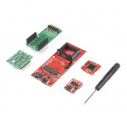
For this example, users will need a MicroMod mikroBUS™ carrier board, STM32 processor board, phillips head screwdriver, Weather Click, MIKROE CODEGRIP for STM32 programmer, 50-100mil JTAG adapter, and access to a computer with the Necto Studio and the CODEGRIP Suite installed:

Users will also need some soldering equipment and a JTAG header to connect the programmer to the board:
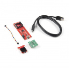
To read the data output from the Weather Click example code, users will also need a Terminal Click, serial breakout board, jumper wires, and a USB cable:
For users who haven't soldered before and/or need to install the CH340 driver for the Serial Basic breakout, the following tutorials should be reviewed before proceeding further:
How to Solder: Through-Hole Soldering
SparkFun Serial Basic CH340C Hookup Guide
How to Install CH340 Drivers
Getting Started with Necto Studio
Hardware Assembly
Hardware assembly is relatively straight forward, attach the STM32 processor board to the MicroMod slot, solder on the JTAG header, insert the Click boards™ into the mikroBUS™ socket, connect the carrier board to the programmer, connect the Serial Basic breakout, and then link the programmer to the computer.
If users haven't done so, solder the JTAG header to the board.
To breakout the serial pins of the mikroBUS™ socket, the Terminal Click board™ needs to be stacked between the Weather Click board™ and the mikroBUS™ socket.
Once the serial pins have been broken out with the Terminal Click board™, users can access the serial pins with a Serial Basic breakout and some jumper wire.
The pin connections are summarized in the table below and illustrated more closely in the images (click to enlarge).
| Terminal Click™ | Serial Breakout | Description |
|---|---|---|
RX |
RXI |
Serial data output from Click board™ to MCU |
TX |
TXO |
Serial data output from MCU to Click board™ |
3.3V |
VCC |
Power input to mikroBUS socket™ |
GND |
GND |
Ground |
Finally, connect the CODEGRIP programmer with a JTAG adapter. Then, connect both the programmer and Serial Basic breakout to the computer.
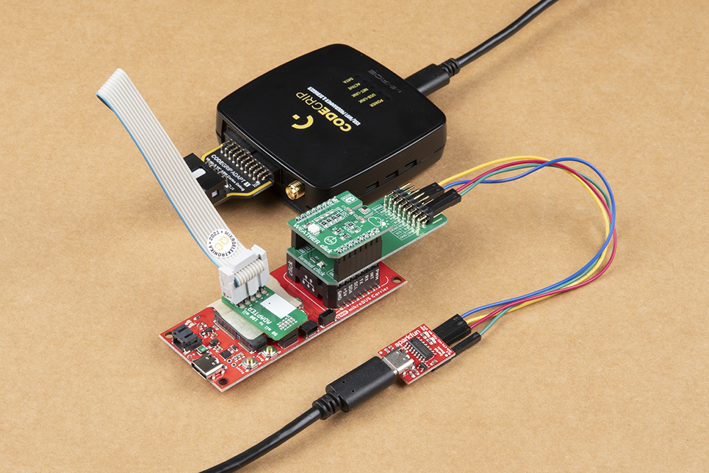
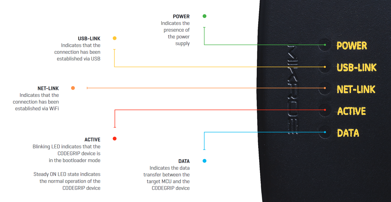
If everything was connected properly, the POWER and ACTIVE, and USB LINK LED indicators on the programmer will turn on. Once the ACTIVE LED indicator stops blinking, the CODEGRIP programmer is ready to be used.
Software Setup
On the computer, users should have Necto Studio and the CODEGRIP Suite installed.
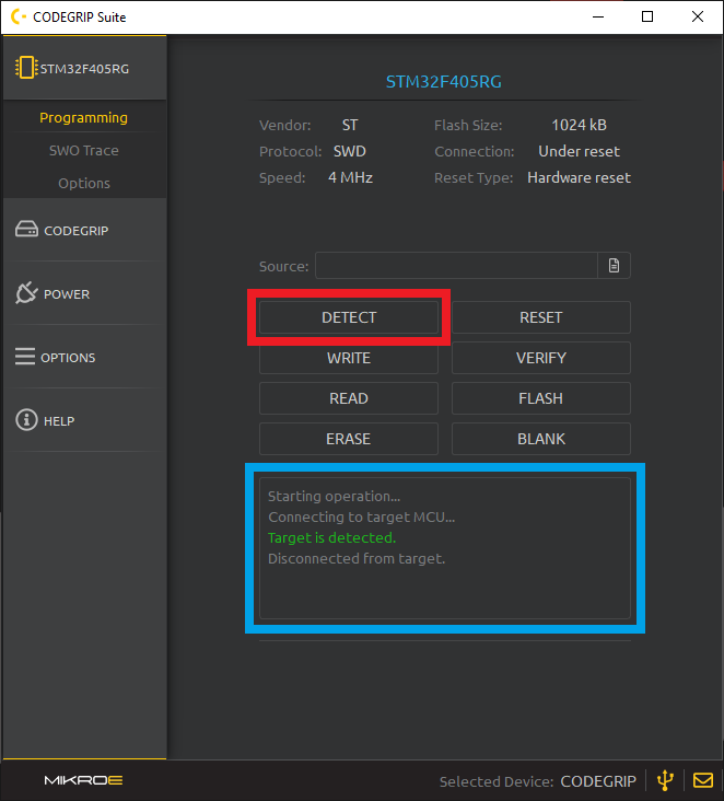
In the CODEGRIP Suite, users will need to link with the programmer and configure the programming target:
- MCU:
STM32F4045RG - Protocol:
SWD - Connection:
Under reset - Halt on Connect:
Enabled
NOTE: Users won't need to enable the power output on the programmer because the power connection from the Serial breakout board. This will provide enough power for the carrier board.After the programmer has been linked and the MCU target has been configured, users should be able to perform a target verification with the detect function.
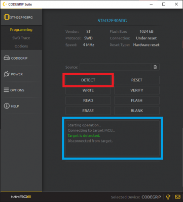 Detecting the target MCU in the CODEGRIP Suite. (Click to enlarge)
For more details, check out the Programmer Configuration section of the Necto Studio getting started guide.
- MCU:
In Necto Studio, if users should have already created a hardware configuration through the Setups page. The hardware configuration should include the following options:
- mikroC AI for ARM compiler
- mikroSDK (latest)
- MicroMod Carrier Board
- STM32F4045RG-Tx (should be only option)
- No display
- CODEGRIP Programmer
- To be able to debug and program the MCU from Necto Studio, users will want to configure the following target option parameters:
Target options for the CODEGRIP programmer in Necto Studio. (Click to enlarge)
- Erase Type:
Erase and unlock - Connection:
Under reset - Hold on Connect:
Enabled
- To be able to debug and program the MCU from Necto Studio, users will want to configure the following target option parameters:
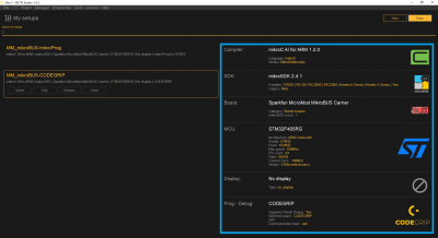 Hardware configuration in Setups page of Necto Studio. (Click to enlarge)
For more details, check out the Setups section of the Necto Studio getting started guide.
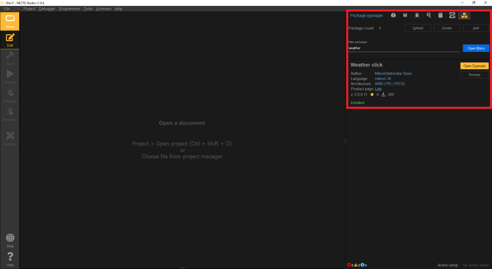
In the package manager of Necto Studio, users will need to install the Weather Click library.
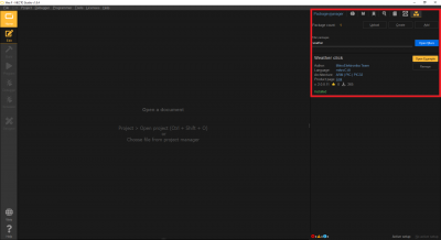 The Weather Click library installed through the Package Manager page of Necto Studio. (Click to enlarge)
For more details, check out the Package Manager section of the Necto Studio getting started guide.
Once the Weather Click library has been installed, users will have access the associated example for the library. From the Package Manager page, users should be able to create a new project by clicking on the Open Example button.
- Users will then need to select their hardware setup. Users should select the hardware configuration for they created for the MicroMod mikroBUS™ carrier board.
- For more details, check out the Package Manager section of the Necto Studio getting started guide.

Running the Example Code
After the project has been created for the Weather Click example, users will be able to program the example onto their carrier board. This can be done either of two methods; however, the simplest method would be to use the Program button in Necto Studio.
To receive and display the serial data output from the example, users will need to open the UART Terminal in Necto Studio by selecting Tools > UART Terminal from the drop down menu.
In the UART Terminal, users will need to:
- Select the Port for the Serial Basic breakout
- Set the Baud rate to
115200 bps Click on the Connect button
 UART Terminal configuration to connect to the Serial Basic breakout. (Click to enlarge)
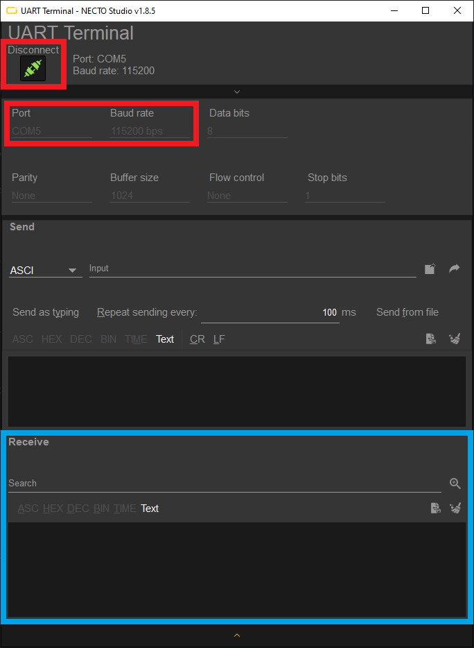
If the connection succeeds, users should then see data from the BME280 sensor being displayed in the Receive text box.
Troubleshooting Tips
Below, we have also included some troubleshooting tips for issues that you may come across.
- One of our employees compiled a great list of troubleshooting tips based on the most common customer issues. This is the perfect place to start.
Hardware
For users looking for technical assistance specifically related to the hardware, click on this link. There you will find, basic troubleshooting tips and instructions to get started with posting a topic in our forum. Our technical support team will do their best to assist you.
Software
For users looking for technical assistance specifically related to the software, click on this link. There users can get started with posting a topic in MikroElektronika forum.
For commercial businesses, MikroElektronika also offers a Premium Technical Support package, which can be purchased from their website.
Sign-in or CODEGRIP Installation Issues
On Windows 10 PCs, if users experience an issues signing in to Necto Studio or come across an Error:UnknownNetworkError error message, their computer may be missing a Microsoft Visual C++ 2010 Runtime Library.
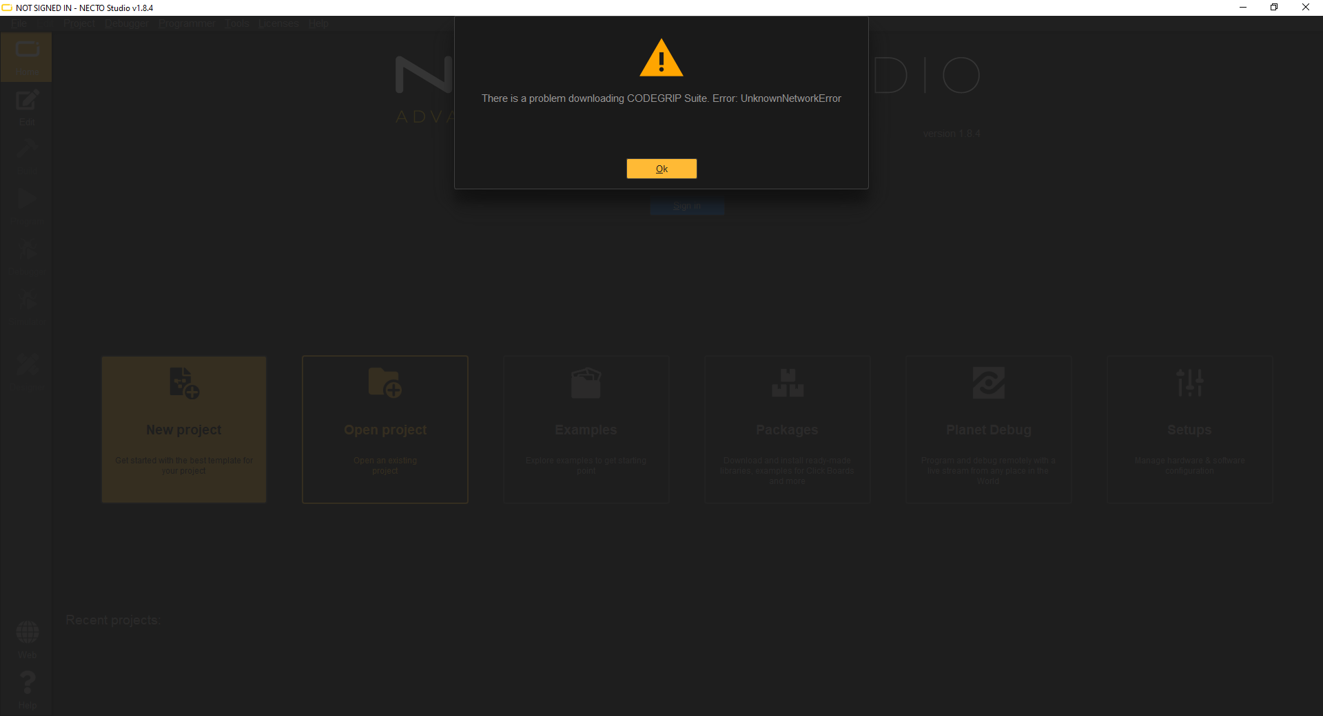
Error:UnknownNetworkError error message. (Click to enlarge) To install the missing Microsoft Visual C++ 2010 Runtime Library, download the vcredist_x64.zip file (or click the button below), extract the folder, and execute the contained installation setup file vcredist_x64.exe.
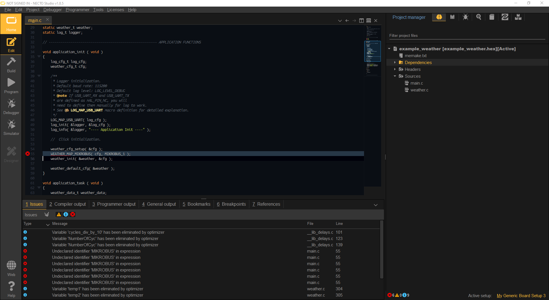
Example Code Compilation Error
Users who select a Generic board in their hardware setup, may run into a compilation error. This error is because the pins for the Generic board are undefined, by default. Users will need to declare the pins utilized by their code for the build to compile.
Programming Issues
To detect a target MCU, it must be at least powered and have the SWD pins connected to the programmer.
Power
The carrier board has to be powered by in order for the programmer to detect the target MCU on the processor board. Users can power the carrier board externally or through the CODEGRIP programmer (by enabling it through the CODEGRIP Suite).
CODEGRIP Suite
Users should verify that they configure the target MCU properly.
Users can also manually program the MCU through the CODEGRIP Suite, by loading the compiled *.hex file of the project, built in Necto Studio and the writing it to the target MCU.
For more details, check out the Programmer and Debugger Configuration section of the Necto Studio getting started guide.
Necto Studio - Target Options
In order to program a MCU through Necto Studio, users will need to configure the Target options of the CODEGRIP programmer when creating their setup:
- Erase Type:
Erase and unlock - Connection:
Under reset - Hold on Connect:
Enabled

No Data Output
If the data doesn't output immediately, try power cycling the carrier board, by disconnecting and reconnecting the power from the Serial Basic breakout.
Otherwise, verify that the MCU is being powered sufficiently. If the MCU isn't being powered sufficiently, it may not run or output data at the appropriate logic levels.
Users can double check the voltage through the CODEGRIP programmer in the CODEGRIP Suite. Open the
POWERmenu and select the newly unfoldedOutputsmenu item. Users should see the the voltage provided to the target MCU in the Measurements section: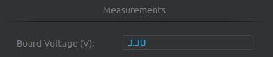 Voltage measurement for power to the target MCU through the CODEGRIP Suite. (Click to enlarge)
Resources and Going Further
For more on the MicroMod mikroBUS™ carrier board, check out the links below:
MicroMod mikroBUS Carrier Documentation
- Schematic
- Eagle Files
- Board Dimensions
- Getting Started with Necto Studio
- mikroBUS Standard
- Qwiic Info Page
- GitHub Hardware Repo
MicroMod Documentation:
For more project inspirations, check out these other MIKROE Click Boards™: