MicroMod SAMD51 Processor Board Hookup Guide
 bboyho,
  Elias The Sparkiest
Arduino Examples
The SAMD51 is a powerful microcontroller. Here are a few examples that highlight some of its functionality.
Example 1: Blink and Hello World!
Now that you have a Processor Board secure in the Carrier Board, let's upload a combined sketch to the board. We will combine the blink and Hello World! sketches into one. Copy and paste the following code in the Arduino IDE. Head to Tools > Board to select the correct board definition (in this case, SparkFun MicroMod SAMD51). Select the correct COM port that the board enumerated to. Hit upload.
language:c
/* MicroMod SAMD51 Blink and Serial Test Code
   by: Ho Yun "Bobby" Chan
   SparkFun Electronics
   updated: November 5, 2021
   date: October 7, 2020
   license: Public Domain - please use this code however you'd like.
   It's provided as a learning tool.

   This code is provided to show how to control the SparkFun
   MicroMod SAMD51's STAT LED within a sketch. It also serves
   to explain the difference between Serial.print() and
   Serial1.print().

*/

//int LED_BUILTIN = 13;  // The STAT LED has a defined Arduino pin
/* Note: STAT LED is connected to pin 13. This is defined in the
   MicroMod SAMD51 board files already as macros (e.g. PIN_LED, LED_BUILTIN)
   so we can comment this out.
*/


void setup()
{
  pinMode(LED_BUILTIN, OUTPUT);  // Set RX LED as an output
  // TX LED is set as an output behind the scenes

  Serial.begin(9600); //This pipes to the serial monitor
  //while (!Serial) ; // Wait for Serial Monitor to open for Processors with Native USB
  Serial.println("Initialize Serial Monitor");

  Serial1.begin(9600); //This is the UART, pipes to sensors attached to board
  Serial1.println("Initialize Serial Hardware UART Pins");
}

void loop()
{
  Serial.println("Hello world!");  // Print "Hello World" to the Serial Monitor
  Serial1.println("Hello! Can anybody hear me?");  // Print "Hello!" over hardware UART

  digitalWrite(LED_BUILTIN, LOW);   // set the LED_BUILTIN ON
  delay(1000);              // wait for a second

  digitalWrite(LED_BUILTIN, HIGH);    // set the LED_BUILTIN OFF
  delay(1000);              // wait for a second
}
Check out the MicroMod SAMD51's built-in LED. The LED should blink every second.
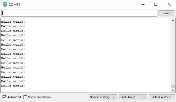
Open the Arduino IDE's serial monitor set at 9600 baud. You should see every programmer's favorite two-word phrase.
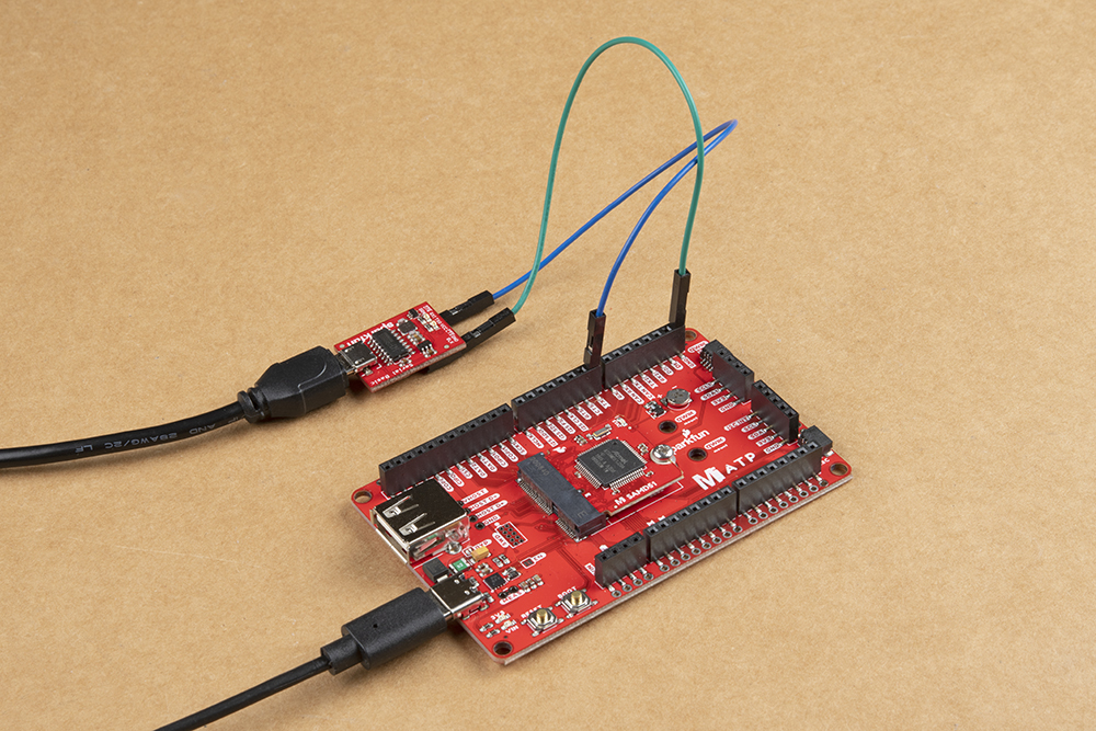
Want to go the extra mile? Grab a 3.3V USB-to-serial converter (in this case, we are using the Serial Basic Breakout CH340). Then connect GND to GND using a M/M jumper wire. Add another M/M jumper wire between TX from the MicroMod ATP Carrier board and the RXI pin of the USB-to-serial converter. Connect the appropriate USB cable to the USB-to-serial converter.
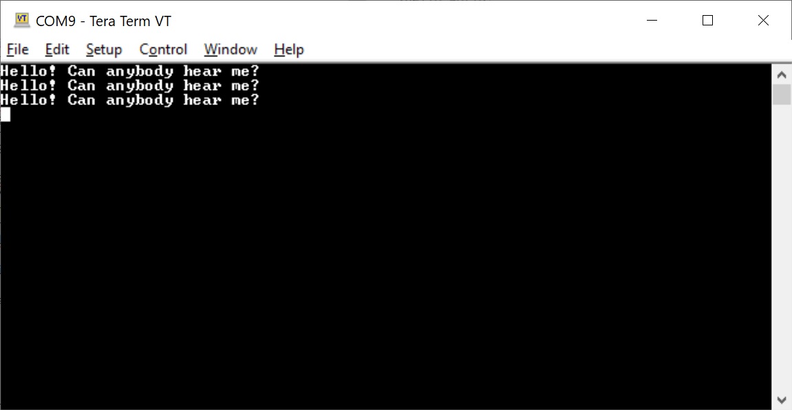
Open another serial terminal (in this case, we'll use Tera Term on a Windows) and connect to the USB-to-serial converter at 9600 baud. You should see a different message being sent from the hardware serial pin.
Example 2: Qwiic-Enabled Device Qwiic Distance Sensor (VL53L1X)
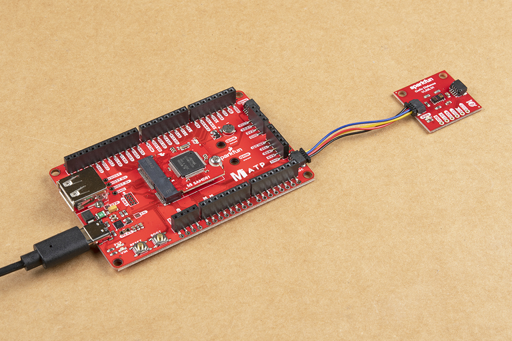
There's a plethora of Qwiic-enabled devices available to connect. In this example, we will be using a Qwiic distance sensor to test. If you have not already, head over to the Qwiic Distance Sensor's (VL53L1X) tutorial to install the library.
Qwiic Distance Sensor (VL53L1X, VL53L4CD) Hookup Guide
February 10, 2022
Connect the distance sensor to the Qwiic connector. Make sure to connect to the one labeled I2C. There is a second port labeled as I2C1. You would need to adjust the code in order to use the second I2C port.
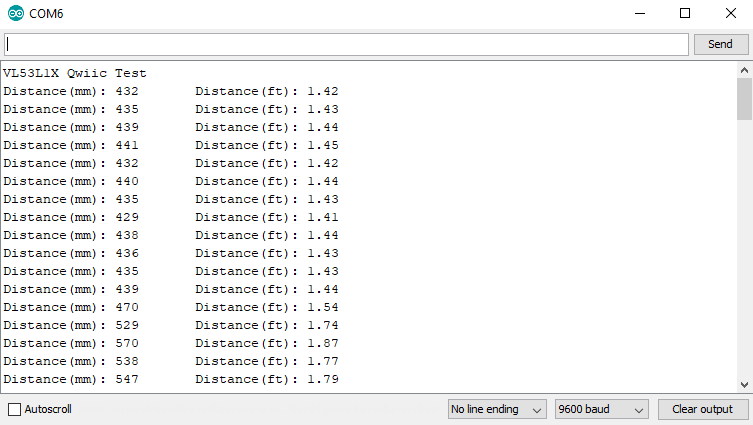
For simplicity, we'll use the first example just like the tutorial. Open up the first example by heading to File > Examples > SparkFun VL53L1x 4M Laser Distance Sensor > Example1_ReadDistance. If you have not already, head to Tools > Board to select the correct board definition (in this case, SparkFun MicroMod SAMD51). Select the correct COM port that the board enumerated to. Hit upload.
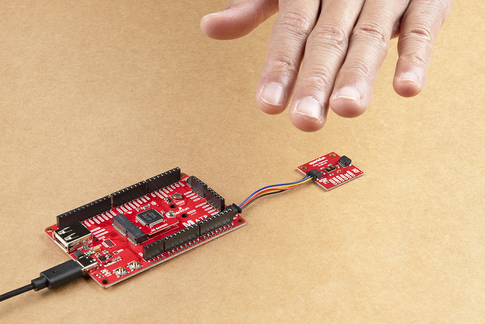
Open a the Arduino Serial Monitor at 9600 baud and start moving your hand over the sensor.
You should see an output similar to the image below. The values will vary depending on the distance away from the sensor.
What's next? Try combining the distance sensor example with the HID keyboard/mouse library to wake up a Raspberry Pi from it's screensaver whenever an object is in front of the sensor. Better yet, try adding some buttons and writing code to make a game controller for a computer.