MicroView Digital Compass
 AGlass0fMilk
Hardware Hookup
It might seem complicated, but there are only a few basic blocks of the circuit: power, brains, the level-shifter, and the sensor.
Powering your circuit
If you aren't using battery power you can just ignore the PowerCell. Be sure to only power the MAG3110 with 3.3V. If you give it 5V, it might get damaged! The MicroView has an internal 3.3V regulator, but unfortunately it isn't pulled out to the pins. Instead, you can use an external 3.3V LDO regulator. See the datasheet for how to hook this up (it's really simple!).
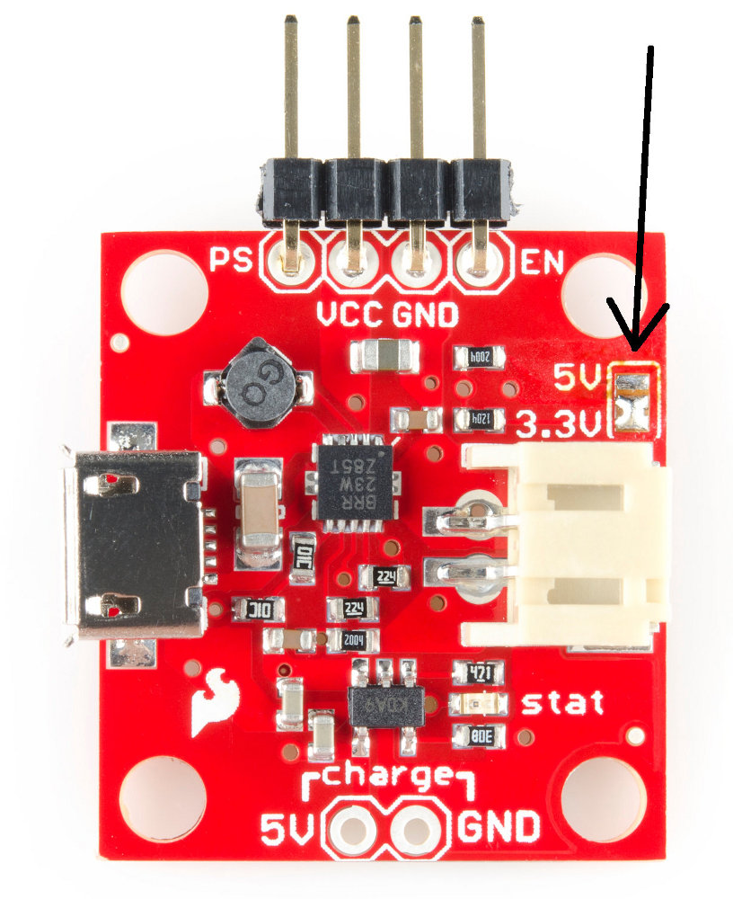
The PowerCell features a selectable voltage output -- either 5V (default) or 3.3V. In order to use it with our project, we need to change the output to 3.3V. There is a solder jumper that selects this. Use some solder wick to remove the solder, and bridge the center pad and the pad that says "3.3V".
If you are still unsure about your connection, see the PowerCell Quickstart Guide.
With either method, make sure to check the voltage output of your power source using a multimeter before you hook anything up to it!
Wiring up the MicroView
The MicroView has an internal 5V boost regulator. This means you can give it lower supply voltages (down to 3.3V) and it will boost them up to the 5V it needs. This makes it very easy to power our MicroView from the 3.3V output of the PowerCell.
Conveniently, the MicroView brings this 5V out to an external pin for use in other parts of our circuit. This is good because we need it to use the logic level shifter.
Recall the pinout of the MicroView:
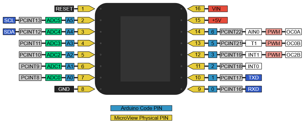
Connect the 3.3V source to the VIN pin of the MicroView, and connect the GND pin to ground. Voila! The MicroView has power.
Connecting the level shifter
The level shifter allows higher voltage (5V) logic devices to talk to lower voltage (3.3V) logic devices without damage or miscommunication. For more information on logic levels, see this guide, and, to learn more about how to hook up the level shifter, see this guide
Here's the level shifter we will be using:

Notice there's a high voltage side and a low voltage side. Connect the high voltage source, "HV", to the 5V pin of the MicroView, and connect GND to ground.
For the low voltage side, connect LV to 3.3V and GND to ground.
I2C Communication
The MAG3110 sensor communicates over I2C. This protocol is nice because it only requires two wires between the devices. Namely, SDA (serial data) and SCL (serial clock). From the pinout shown before, you can see the MicroView has SCL and SDA on pins 2 and 3, respectively.
We only have to shift these two outputs, so connect the SCL and SDA of the MicroView to HV1 and HV2 of the level shifter.
Wiring the MAG3110 Sensor
The MAG3110 sensor is a 3-axis magnetometer that can be used to sense the strength of magnetic fields. This data can be used to find magnetic north! Check out the MAG3110 hookup guide for more on how to use this sensor!
The MAG3110 breakout only has a few pins we need to connect.
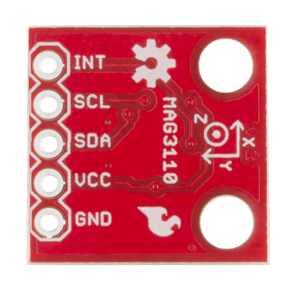
The MAG3110 can only handle voltages up to 3.6V, so be sure to connect VCC to 3.3V and not 5V. The GND pin goes to ground, and SCL and SDA should go to LV1 and LV2 of the level shifter. Make sure you don't have SCL or SDA swapped around on either side of the level shifter or you won't be able to talk to the sensor.
Completed Circuit
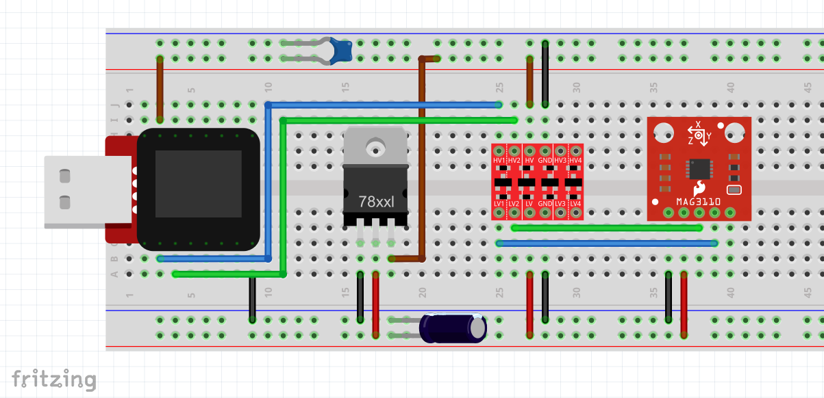
The circuit should now be complete. Make sure to check your connections before you plug in the battery.
If you chose to use USB power (using the MicroView Programmer) and an external 3.3V regulator, this circuit is found below. Don't worry too much about the capacitors, they're just filtering capacitors recommended by the regulator's datasheet.
If you used the more portable battery-based PowerCell circuit, you can follow this circuit shown below.
