MIDI Shield Hookup Guide
 Byron J.
Example #2: MIDI-to-control-voltage
If you're interested in building a MIDI synthesizer, the MIDI Shield is quite capable. There is an example in the Forty Seven Effects documentation that uses the Arduino tone library as a simple MIDI instrument. We're going to build a little more ambitious system, that allows us to play the Moog Werkstatt with real keys. This is useful because the Werkstatt is usually played with an array of tiny tactile switches.
The Werkstatt is a good candidate for this project because it has a header on which it receives external control voltages. We'll be generating the following voltages:
- The pitch control voltage (CV) is a DC voltage that represents which key is currently pressed. The oscillator on the Werkstatt raises its pitch an octave for every volt present on this input; in other words, a semitone is 1/12th of a volt.
- The gate signal is an on/off indicator -- when one or more keys on the MIDI controller are held, the gate is high. When no keys are pressed, the gate is low. The Werkstatt responds to the gate by triggering the envelope generator, which in turn drives the VCF and VCA.
- There's a second analog control voltage from the converter that represents modulation wheel (continuous controller #0) position. It can be patched into other inputs on the Werkstatt, such as LFO rate or filter cutoff.
Materials
This project requires the following parts.
It also needs a MIDI keyboard controller and a MIDI cable.
Construction
Construction and testing is a little more involved that the other two projects.
First, we need a ground wire in the Werkstatt. In this case, a green wire is wrapped around one of the screw posts inside and out through a gap in the front of the chassis.

DAC Board Assembly
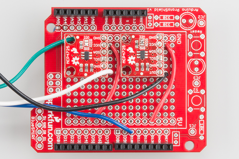
After that, prepare the DACs, and put them on the proto shield. The DACs come configured using the same I2C address (0x60) -- on one of the DAC breakouts, cut the traces on the pullup resistor jumper on the back of the board, and switch its address to 0x61 by switching the ADDR jumper to VCC.
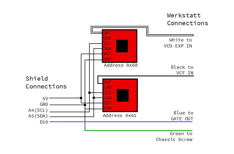
The two DACs are soldered onto strips of breakaway headers and then onto the proto shield. The following connections were made on the shield with wire:
- Their VCC pins were tied to the 5V pin.
- The SDA pins were tied to A4.
- The SCL pins were tied to A5.
- Longer wires were connected to the DAC outputs -- we selected a blue one, a white one, and a black one.
- The white wire is the output of the DAC at the default address.
- The black wire is the output of the other DAC.
- The blue wire was connected to D10.
- The green ground wire from inside the Werkstatt is tied to a
GNDpin on the proto shield.
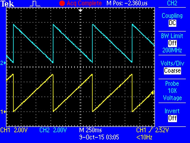
Testing the DACs
Once the DACs are wired onto the protoshield, put the shield on the RedBoard to test them. Loading the DAC Integration Test sketch to verify that they're working. It verifies that they're working correctly and communicating on the correct addresses by generating opposing full-scale sawtooth waves.
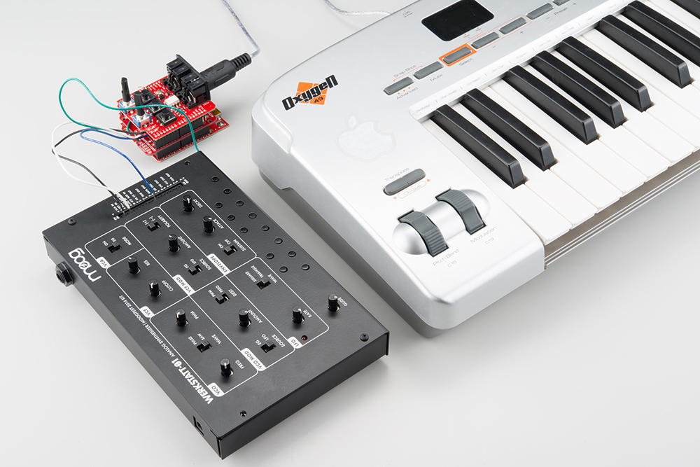
Connections
Once you're confident that the DACs are working, you can put the MIDI shield on top of the stack, and connect the Werkstatt and MIDI controller. The MIDI controller is connected to the MIDI input on the shield. The wires from the protoshield are connected to the Werkstatt as follows:
- The white wire gets plugged into the
VCO EXPinput. - The black wire goes into the
VCF IN. - The blue wire is connected to the
GATE OUT.
Firmware
The firmware for this project is a little more complex, requiring ancillary *.CPP and *.H files. Get all three files from the
GitHub folder for the project, and store them in a directory named MIDI-CV. When you open MIDI-CV.ino, it should also open notemap.h and .cpp. Compile and load the sketch, then press some keys on your MIDI controller.
This example uses a more sophisticated interface to the 47 Effects library: rather than polling the library for new messages, it installs callback routines for the relevant message categories. It's also configured to listen in Omni mode - it should respond to messages on any MIDI channel.
In Operation
With a range of 5V to work with, the design target was to have 4 octaves of control voltage, plus roughly +/-1/2 octave bend range. If multiple keys are held, the CV represents the lowest note.
The MIDI-CV sketch includes a fun bonus -- an arpeggiator! If you hold more than one controller key at a time, the converter will periodically cycle between the keys.
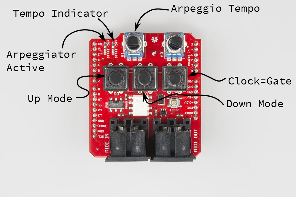
- Button D2 enables the arpeggiator in up mode.
- Button D3 enables the arpeggiator in Down mode.
- Button D4 changes the gate to follow the arpeggiator clock.
- Pot A1 controls the rate of arpeggiation.
- The red LED (D7) displays arpeggiator tempo.
- The green LED (D6) illuminates when the arpeggiator is enabled.
You can switch between up and down modes while the arpeggiator is running. To disable the arpeggiator, press the button for the current mode a second time.
Calibration
The convention for control voltage is that increasing the voltage by one volt will cause the pitch to raise by an octave; 1/12th of a volt (0.08333V) corresponds to a semitone.
The DACs are also referenced to VCC on the board, nominally 5V in this case. Different power supplies will change the scaling of the CV -- the test unit behaved a little differently when powered from the USB connection (yielding VCC of 5.065 V) and from a 9V wall-wart supply plugged into the barrel jack (resulting in VCC of 5.008 V). When you adjust the scaling, it's important that you're powering the system as it will be deployed!
The intonation can be adjusted at both ends of the interface described here. Trimpot VR5 in the Werkstatt allows for Volt-to-Octave adjustments. In the Sketch, the constant DAC_CAL is also used to change the CV scaling. Since it's adjustable at both ends, it can lead to confusion if you start adjusting them at the same time.
The key to preventing that confusion is remembering the Volt/Octave convention. Independently adjust each end of the interface so that volts and octaves correspond. We calibrated the system using the following procedure:
- First the Arduino side is calibrated to produce a 1V step for an octave between note-on messages
- A DC Voltmeter was connected to the CV output of the DAC board.
- Ascending octaves were played on the keyboard.
- The
DAC_CALvalue was adjusted until those octaves resulted in 1VDC changes to the CV output.- In this case, the default value of 6826 worked fairly well.
- The resulting voltages were 0.483V, 1.487V, 2.485V, 3.484V, and 4.485V.
- Once the CV has been adjusted to 1V/8ve, VR5 in the Werkstatt can be adjusted to volt/octave response.
- We used a frequency counter function in an oscilloscope to check the frequency, measured at the
VCO outpatch point. It was doublechecked with a digital guitar tuner. - We started by hopping back and forth between low C and the next C up, then moving to higher octaves as the intonation got better.
- If you tune the high A to 440 Hz, working backwards to the lowest A on a 4-octave keyboard gives you 440 Hz, 220 Hz, 110 Hz and 55 Hz.
- The Werkstatt is most accurate in the lower registers, and tends to run a little flat in the upper registers.
- The tuning pot on the panel is also somewhat touchy. While you're building this interface, you might also consider adding Moog's Fine Tuning Mod.
- We used a frequency counter function in an oscilloscope to check the frequency, measured at the
Troubleshooting
This project was developed using a soft serial port for MIDI and the hardware serial port to print debug messages. Once it was working, the debug printing was disabled, and MIDI was reverted to the hardware serial port.
If you want to enable debug printing:
- Start by adjusting SJ1 and SJ2 for MIDI on the soft serial pins.
- Amend the declaration of the MIDI instance to create and use the soft serial port.
- Change the
VERBOSEmacro to1