ML8511 UV Sensor Hookup Guide
 Nate
Nate 
Using the ML8511
The ML8511 sensor is very easy to use. It outputs a analog voltage that is linearly related to the measured UV intensity (mW/cm2). If your microcontroller can do an analog to voltage conversion, then you can detect the level of UV.
Load the ML8511 UV Sensor Read Example onto the Arduino of your choice.
language:c
/*
ML8511 UV Sensor Read Example
By: Nathan Seidle
SparkFun Electronics
Date: January 15th, 2014
License: This code is public domain but you buy me a beer if you use this and we meet someday (Beerware license).
The ML8511 UV Sensor outputs an analog signal in relation to the amount of UV light it detects.
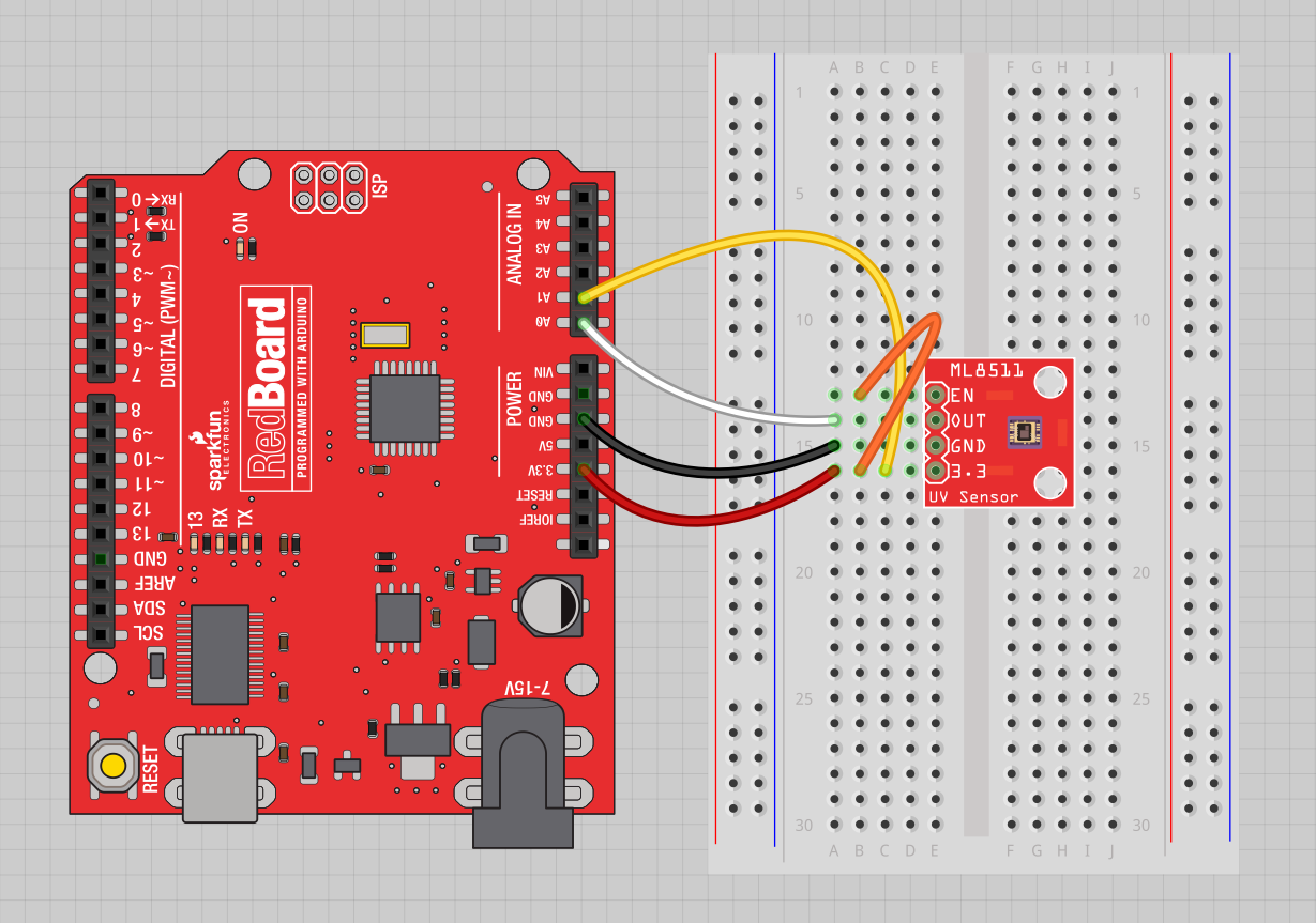
Connect the following ML8511 breakout board to Arduino:
3.3V = 3.3V
OUT = A0
GND = GND
EN = 3.3V
3.3V = A1
These last two connections are a little different. Connect the EN pin on the breakout to 3.3V on the breakout.
This will enable the output. Also connect the 3.3V pin of the breakout to Arduino pin 1.
This example uses a neat trick. Analog to digital conversions rely completely on VCC. We assume
this is 5V but if the board is powered from USB this may be as high as 5.25V or as low as 4.75V:
http://en.wikipedia.org/wiki/USB#Power Because of this unknown window it makes the ADC fairly inaccurate
in most cases. To fix this, we use the very accurate onboard 3.3V reference (accurate within 1%). So by doing an
ADC on the 3.3V pin (A1) and then comparing this against the reading from the sensor we can extrapolate
a true-to-life reading no matter what VIN is (as long as it's above 3.4V).
Test your sensor by shining daylight or a UV LED: https://www.sparkfun.com/products/8662
This sensor detects 280-390nm light most effectively. This is categorized as part of the UVB (burning rays)
spectrum and most of the UVA (tanning rays) spectrum.
There's lots of good UV radiation reading out there:
http://www.ccohs.ca/oshanswers/phys_agents/ultravioletradiation.html
https://www.iuva.org/uv-faqs
*/
//Hardware pin definitions
int UVOUT = A0; //Output from the sensor
int REF_3V3 = A1; //3.3V power on the Arduino board
void setup()
{
Serial.begin(9600);
pinMode(UVOUT, INPUT);
pinMode(REF_3V3, INPUT);
Serial.println("ML8511 example");
}
void loop()
{
int uvLevel = averageAnalogRead(UVOUT);
int refLevel = averageAnalogRead(REF_3V3);
//Use the 3.3V power pin as a reference to get a very accurate output value from sensor
float outputVoltage = 3.3 / refLevel * uvLevel;
float uvIntensity = mapfloat(outputVoltage, 0.99, 2.8, 0.0, 15.0); //Convert the voltage to a UV intensity level
Serial.print("output: ");
Serial.print(refLevel);
Serial.print("ML8511 output: ");
Serial.print(uvLevel);
Serial.print(" / ML8511 voltage: ");
Serial.print(outputVoltage);
Serial.print(" / UV Intensity (mW/cm^2): ");
Serial.print(uvIntensity);
Serial.println();
delay(100);
}
//Takes an average of readings on a given pin
//Returns the average
int averageAnalogRead(int pinToRead)
{
byte numberOfReadings = 8;
unsigned int runningValue = 0;
for(int x = 0 ; x < numberOfReadings ; x++)
runningValue += analogRead(pinToRead);
runningValue /= numberOfReadings;
return(runningValue);
}
//The Arduino Map function but for floats
//From: http://forum.arduino.cc/index.php?topic=3922.0
float mapfloat(float x, float in_min, float in_max, float out_min, float out_max)
{
return (x - in_min) * (out_max - out_min) / (in_max - in_min) + out_min;
}
Next, connect the following ML8511 breakout board to Arduino:
- ML8511 / Arduino
- 3.3V = 3.3V
- OUT = A0
- GND = GND
- EN = 3.3V
- Arduino 3.3V = Arduino A1
These last two connections are a little different. Connect the EN pin on the breakout to 3.3V to enable the device. Also connect the 3.3V pin of the Arduino to Arduino analog pin 1.
This example uses a neat trick. Analog to digital conversions rely completely on VCC. We assume this is 5.0V, but if the board is powered from USB this may be as high as 5.25V or as low as 4.75V. Because of this unknown window, it makes the ADC on the Arduino fairly inaccurate. To fix this, we use the very accurate onboard 3.3V reference (accurate within 1%). So by doing an analog to digital conversion on the 3.3V pin (by connecting it to A1) and then comparing this reading against the reading from the sensor, we can extrapolate a true-to-life reading, no matter what VIN is (as long as it's above 3.4V).
For example, we know the ADC on the Arduino will output 1023 when it reads VCC. If we read 669 from the connection to 3.3V, what is the voltage powering the Arduino? It's a simple ratio!
VCC / 1023 = 3.3V / 669
Solving for VCC, we get 5.05V. If you've got a digital multimeter, you can verify the 5V pin on your Arduino.
Now that we know precisely what VCC is, we can do a much more accurate ADC on the UV voltage:
UV_Voltage / uvLevel = 3.3 / refLevel
uvLevel is what we read from the OUT pin. refLevel is what we read on the 3.3V pin. Solving for UV_Voltage, we can get an accurate reading.
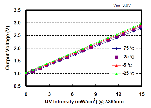
Mapping the UV_Voltage to intensity is straight forward. No UV light starts at 1V with a maximum of 15mW/cm2 at around 2.8V. Arduino has a built-in map() function, but map() does not work for floats. Thanks to users on the Arduino forum, we have a simple mapFloat() function:
//The Arduino Map function but for floats
//From: http://forum.arduino.cc/index.php?topic=3922.0
float mapfloat(float x, float in_min, float in_max, float out_min, float out_max)
{
  return (x - in_min) * (out_max - out_min) / (in_max - in_min) + out_min;
}
The following line converts the voltage read from the sensor to mW/cm2 intensity:
float uvIntensity = mapfloat(outputVoltage, 0.99, 2.8, 0.0, 15.0); //Convert the voltage to a UV intensity level
Test your sensor by shining daylight or a UV LED onto the sensor. We've also found that a bright LED flashlight will change the reading slightly. What other devices around your house might output UV?