Modifying Your EL Wire Inverter
 bboyho
 Introduction
In this tutorial, we will modify the 12V EL wire inverter to power the EL Sequencer or EL Escudo Dos off a single power supply.
Required Materials
To follow along with this tutorial, you will need the following materials at a minimum. You may not need everything though depending on what you have. Add it to your cart, read through the guide, and adjust the cart as necessary.
Tools
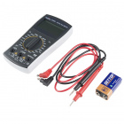
You will need a soldering iron, solder, and general soldering accessories. You will also need a screwdriver and multimeter for testing.


Suggested Reading
If you aren’t familiar with the following concepts, we recommend checking out these tutorials before continuing.
How to Solder: Through-Hole Soldering
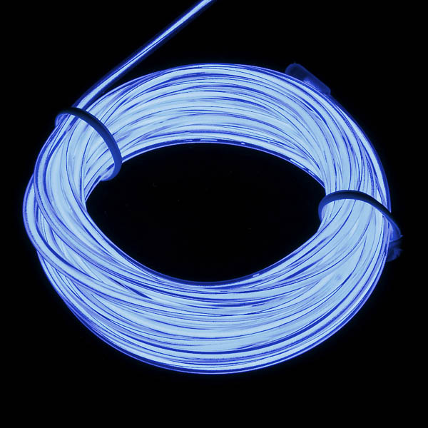
Getting Started with Electroluminescent (EL) Wire
EL Sequencer/Escudo Dos Hookup Guide
Hacking Your EL Wire Inverter's Input
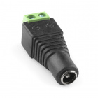
By default, the DC input on the 12V inverter has a connector that accepts a barrel jack connector. This is usually a great feature but we'd rather have that input be a JST connector so we can hook it directly to the EL Sequencer/EL Escudo Dos off a single power supply. Don't worry, we can easily hack one in. Remove the QC sticker on the back of the 12V EL inverter. Using a Phillips screwdriver, open the inverter's enclosure.

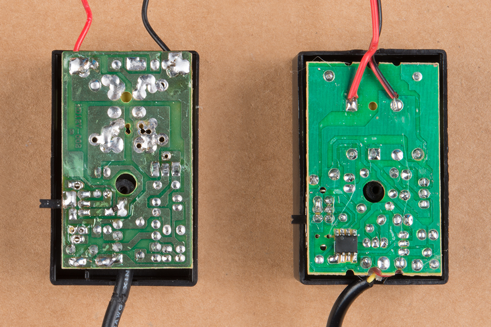
Remove the screw and open the case. The PCB will look different depending on when you ordered the 12V inverter. The inverter on the left is from an older model as opposed to the one on the right. Regardless of how the PCBs look, they will still function the same.
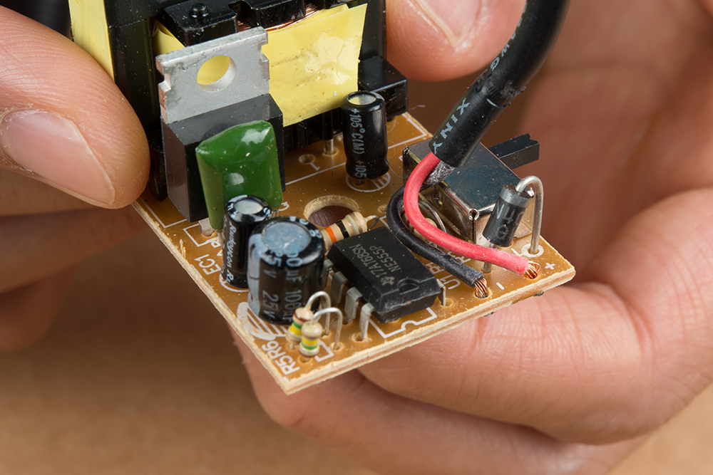
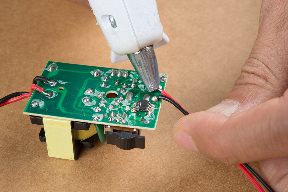
Remove the board from the enclosure so that we can remove the existing wires connected to the barrel jack connector. The wires with the black sheath will be the ones that we will be desoldering. On newer 12V inverters, there should be some hot glue between the wires and PCB. This is for strain relief. If there is hot glue, carefully separate it from the cable and components on the 12V inverter. Desolder the wires connected by heating the pin or PTH pad. If necessary, give the PTH pad a small bump on the table with the slap method to remove any solder before threading new wire through it. If the diode's pin is already soldered on the PTH pad, the wire would need to be soldered to the joint. Feel free to keep the wires connected to the barrel jack in your parts bin for a different project.
Take note of what color wire is connected to the PTH and which side the wires were removed. The PCB may be different depending on when it was manufactured so there may not be any silkscreen indicating the input voltage for "+" and "-". The images in the center and far right did not have any silkscreen associated with the wiring. Usually the "+" is connected to the anode of the diode. In this case, we desoldered the wires from the PCB as shown in sample 3.
 |
 |
 |
| Sample 1 | Sample 2 | Sample 3 |
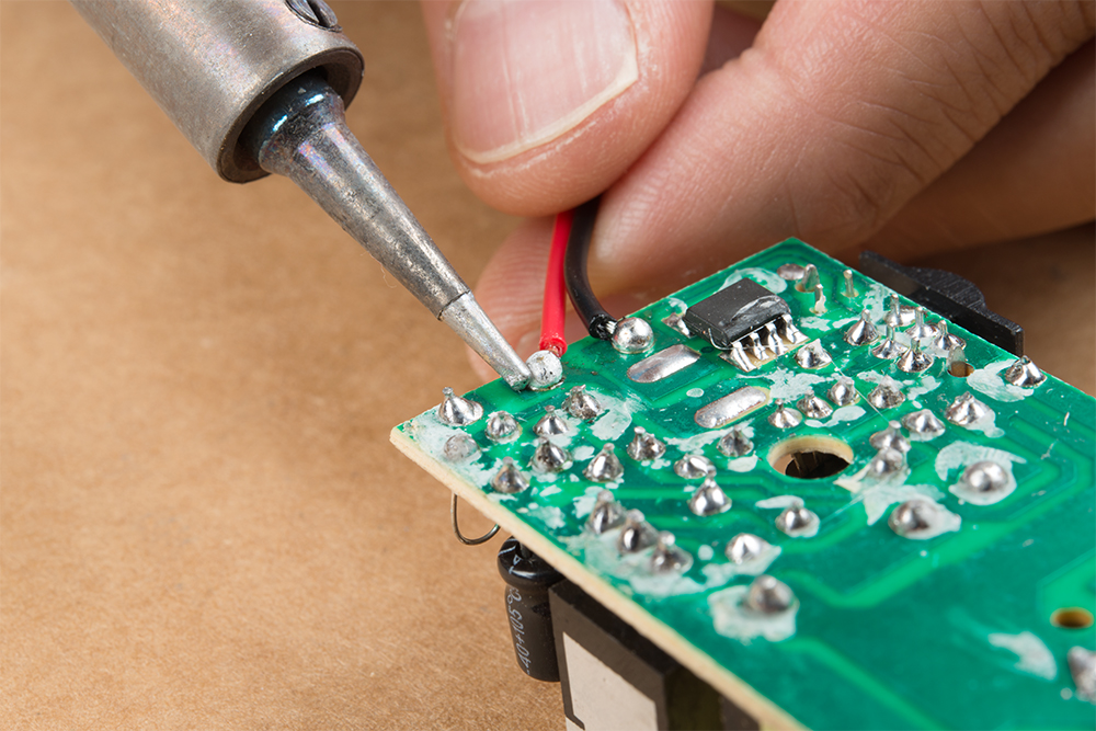
Solder the new JST pigtail to the board. We'll be adding the wires to the bottom of the PCB. To be consistent with the wire colors for the input voltage, we will be connecting the red wire to the pad or pin that is connected to the diode's anode pin. Then we will be connecting the black wire to the other pad or pin that was desoldered.
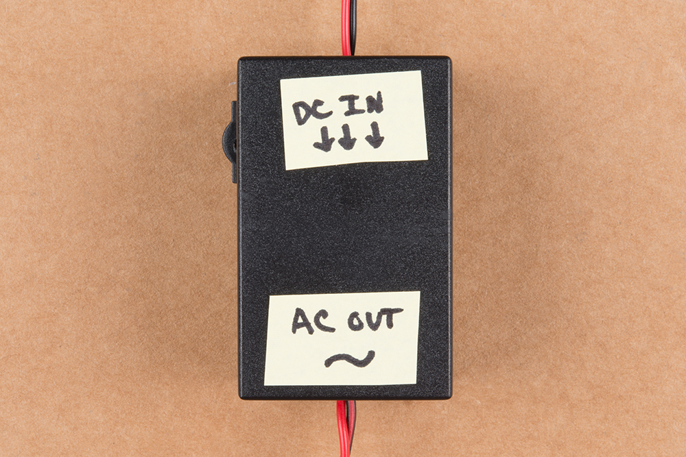
Insert the board back into its respective enclosure while ensuring that the wires are between the openings. Re-insert the screw and tighten. Since the wire colors are the same, try labeling the EL inverter with a marker or tape to indicate the side that is the DC input and AC output. Usually the input voltage is closest to the switch.
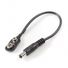
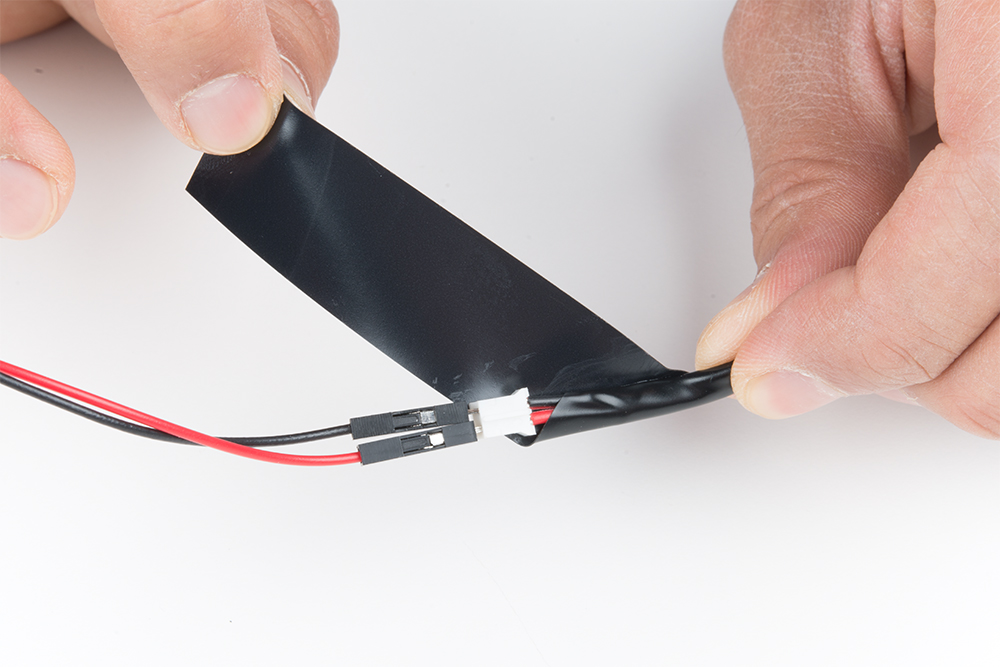
Before powering up, insert jumper wire between your power adapter and DC input similar to how EL wire was tested in the Getting Started Guide. Since we are using the JST pigtail assembly, you will need to remove the mating connector for the JST. Add extra part to your parts bin for future projects! Keep in mind that the DC input has a polarity so VIN should be connected to the red wire and GND to black the wire. Then insert jumper wires between the AC output and EL Wire. If you need, feel free to add some electrical tape as a precaution when handling the AC output.
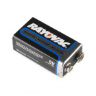
Insert the wall adapter to an outlet (or add a 9V battery if you are using this in a remote setup) to the connection to test. Using the wires connecting to the DC input, touch the red wire to the center tip of the barrel jack and the black wire to the sleeve of the wall adapter. Flip the switch if you do not see the EL powering up. The EL wire should blink or stay on depending on the mode that is used.
Now that we have modified the EL Inverter, the next step is to use it with the EL Sequencer or EL Escudo Dos! Plug the DC input you just made into the "DC TO INVERTER" connector, plug the AC output into the "AC FROM INVERTER" connector, and we're ready to fire things up! For more information, check out the guide below to adjust the solder jumper on the board before connecting.
EL Sequencer/Escudo Dos Hookup Guide
December 3, 2015
Resources and Going Further
Need some inspiration for your next project? Check out some of these related tutorials:
EL Wire Light-Up Dog Harness
Heartbeat Straight Jacket
Sound Reactive EL Wire Costume
Or try hacking the EL inverter battery pack like Bill Porter.