MPU-9250 Hookup Guide
 .Brent.
Library and Example Code
For more information on the algorithms Kris used for the Attitude and Heading Reference System (AHRS), check out the open source IMU and AHRS algorithms
Our version is mostly a conversion to make it follow the Arduino library format. You can use the Arduino IDE's library manager by searching for "SparkFun MPU-9250" as detailed in this tutorial. Or you can manually install the library from the GitHub repository by downloading the *.zip linked below:
#include <Wire.h>
#include <SPI.h>
language:c
/* MPU9250 Basic Example Code
by: Kris Winer
date: April 1, 2014
license: Beerware - Use this code however you'd like. If you
find it useful you can buy me a beer some time.
Modified by Brent Wilkins July 19, 2016
Demonstrate basic MPU-9250 functionality including parameterizing the register
addresses, initializing the sensor, getting properly scaled accelerometer,
gyroscope, and magnetometer data out. Added display functions to allow display
to on breadboard monitor. Addition of 9 DoF sensor fusion using open source
Madgwick and Mahony filter algorithms. Sketch runs on the 3.3 V 8 MHz Pro Mini
and the Teensy 3.1.
SDA and SCL should have external pull-up resistors (to 3.3V).
10k resistors are on the EMSENSR-9250 breakout board.
Hardware setup:
MPU9250 Breakout --------- Arduino
VDD ---------------------- 3.3V
VDDI --------------------- 3.3V
SDA ----------------------- A4
SCL ----------------------- A5
GND ---------------------- GND
*/
#include "quaternionFilters.h"
#include "MPU9250.h"
#ifdef LCD
#include <Adafruit_GFX.h>
#include <Adafruit_PCD8544.h>
// Using NOKIA 5110 monochrome 84 x 48 pixel display
// pin 9 - Serial clock out (SCLK)
// pin 8 - Serial data out (DIN)
// pin 7 - Data/Command select (D/C)
// pin 5 - LCD chip select (CS)
// pin 6 - LCD reset (RST)
Adafruit_PCD8544 display = Adafruit_PCD8544(9, 8, 7, 5, 6);
#endif // LCD
#define AHRS false // Set to false for basic data read
#define SerialDebug true // Set to true to get Serial output for debugging
// Pin definitions
int intPin = 12; // These can be changed, 2 and 3 are the Arduinos ext int pins
int myLed = 13; // Set up pin 13 led for toggling
#define I2Cclock 400000
#define I2Cport Wire
#define MPU9250_ADDRESS MPU9250_ADDRESS_AD0 // Use either this line or the next to select which I2C address your device is using
//#define MPU9250_ADDRESS MPU9250_ADDRESS_AD1
MPU9250 myIMU(MPU9250_ADDRESS, I2Cport, I2Cclock);
void setup()
{
Wire.begin();
// TWBR = 12; // 400 kbit/sec I2C speed
Serial.begin(38400);
while(!Serial){};
// Set up the interrupt pin, its set as active high, push-pull
pinMode(intPin, INPUT);
digitalWrite(intPin, LOW);
pinMode(myLed, OUTPUT);
digitalWrite(myLed, HIGH);
#ifdef LCD
display.begin(); // Ini8ialize the display
display.setContrast(58); // Set the contrast
// Start device display with ID of sensor
display.clearDisplay();
display.setTextSize(2);
display.setCursor(0,0); display.print("MPU9250");
display.setTextSize(1);
display.setCursor(0, 20); display.print("9-DOF 16-bit");
display.setCursor(0, 30); display.print("motion sensor");
display.setCursor(20,40); display.print("60 ug LSB");
display.display();
delay(1000);
// Set up for data display
display.setTextSize(1); // Set text size to normal, 2 is twice normal etc.
display.setTextColor(BLACK); // Set pixel color; 1 on the monochrome screen
display.clearDisplay(); // clears the screen and buffer
#endif // LCD
// Read the WHO_AM_I register, this is a good test of communication
byte c = myIMU.readByte(MPU9250_ADDRESS, WHO_AM_I_MPU9250);
Serial.print(F("MPU9250 I AM 0x"));
Serial.print(c, HEX);
Serial.print(F(" I should be 0x"));
Serial.println(0x71, HEX);
#ifdef LCD
display.setCursor(20,0); display.print("MPU9250");
display.setCursor(0,10); display.print("I AM");
display.setCursor(0,20); display.print(c, HEX);
display.setCursor(0,30); display.print("I Should Be");
display.setCursor(0,40); display.print(0x71, HEX);
display.display();
delay(1000);
#endif // LCD
if (c == 0x71) // WHO_AM_I should always be 0x71
{
Serial.println(F("MPU9250 is online..."));
// Start by performing self test and reporting values
myIMU.MPU9250SelfTest(myIMU.selfTest);
Serial.print(F("x-axis self test: acceleration trim within : "));
Serial.print(myIMU.selfTest[0],1); Serial.println("% of factory value");
Serial.print(F("y-axis self test: acceleration trim within : "));
Serial.print(myIMU.selfTest[1],1); Serial.println("% of factory value");
Serial.print(F("z-axis self test: acceleration trim within : "));
Serial.print(myIMU.selfTest[2],1); Serial.println("% of factory value");
Serial.print(F("x-axis self test: gyration trim within : "));
Serial.print(myIMU.selfTest[3],1); Serial.println("% of factory value");
Serial.print(F("y-axis self test: gyration trim within : "));
Serial.print(myIMU.selfTest[4],1); Serial.println("% of factory value");
Serial.print(F("z-axis self test: gyration trim within : "));
Serial.print(myIMU.selfTest[5],1); Serial.println("% of factory value");
// Calibrate gyro and accelerometers, load biases in bias registers
myIMU.calibrateMPU9250(myIMU.gyroBias, myIMU.accelBias);
#ifdef LCD
display.clearDisplay();
display.setCursor(0, 0); display.print("MPU9250 bias");
display.setCursor(0, 8); display.print(" x y z ");
display.setCursor(0, 16); display.print((int)(1000*myIMU.accelBias[0]));
display.setCursor(24, 16); display.print((int)(1000*myIMU.accelBias[1]));
display.setCursor(48, 16); display.print((int)(1000*myIMU.accelBias[2]));
display.setCursor(72, 16); display.print("mg");
display.setCursor(0, 24); display.print(myIMU.gyroBias[0], 1);
display.setCursor(24, 24); display.print(myIMU.gyroBias[1], 1);
display.setCursor(48, 24); display.print(myIMU.gyroBias[2], 1);
display.setCursor(66, 24); display.print("o/s");
display.display();
delay(1000);
#endif // LCD
myIMU.initMPU9250();
// Initialize device for active mode read of acclerometer, gyroscope, and
// temperature
Serial.println("MPU9250 initialized for active data mode....");
// Read the WHO_AM_I register of the magnetometer, this is a good test of
// communication
byte d = myIMU.readByte(AK8963_ADDRESS, WHO_AM_I_AK8963);
Serial.print("AK8963 ");
Serial.print("I AM 0x");
Serial.print(d, HEX);
Serial.print(" I should be 0x");
Serial.println(0x48, HEX);
#ifdef LCD
display.clearDisplay();
display.setCursor(20,0); display.print("AK8963");
display.setCursor(0,10); display.print("I AM");
display.setCursor(0,20); display.print(d, HEX);
display.setCursor(0,30); display.print("I Should Be");
display.setCursor(0,40); display.print(0x48, HEX);
display.display();
delay(1000);
#endif // LCD
if (d != 0x48)
{
// Communication failed, stop here
Serial.println(F("Communication failed, abort!"));
Serial.flush();
abort();
}
// Get magnetometer calibration from AK8963 ROM
myIMU.initAK8963(myIMU.factoryMagCalibration);
// Initialize device for active mode read of magnetometer
Serial.println("AK8963 initialized for active data mode....");
if (SerialDebug)
{
// Serial.println("Calibration values: ");
Serial.print("X-Axis factory sensitivity adjustment value ");
Serial.println(myIMU.factoryMagCalibration[0], 2);
Serial.print("Y-Axis factory sensitivity adjustment value ");
Serial.println(myIMU.factoryMagCalibration[1], 2);
Serial.print("Z-Axis factory sensitivity adjustment value ");
Serial.println(myIMU.factoryMagCalibration[2], 2);
}
#ifdef LCD
display.clearDisplay();
display.setCursor(20,0); display.print("AK8963");
display.setCursor(0,10); display.print("ASAX ");
display.setCursor(50,10); display.print(myIMU.factoryMagCalibration[0], 2);
display.setCursor(0,20); display.print("ASAY ");
display.setCursor(50,20); display.print(myIMU.factoryMagCalibration[1], 2);
display.setCursor(0,30); display.print("ASAZ ");
display.setCursor(50,30); display.print(myIMU.factoryMagCalibration[2], 2);
display.display();
delay(1000);
#endif // LCD
// Get sensor resolutions, only need to do this once
myIMU.getAres();
myIMU.getGres();
myIMU.getMres();
// The next call delays for 4 seconds, and then records about 15 seconds of
// data to calculate bias and scale.
// myIMU.magCalMPU9250(myIMU.magBias, myIMU.magScale);
Serial.println("AK8963 mag biases (mG)");
Serial.println(myIMU.magBias[0]);
Serial.println(myIMU.magBias[1]);
Serial.println(myIMU.magBias[2]);
Serial.println("AK8963 mag scale (mG)");
Serial.println(myIMU.magScale[0]);
Serial.println(myIMU.magScale[1]);
Serial.println(myIMU.magScale[2]);
// delay(2000); // Add delay to see results before serial spew of data
if(SerialDebug)
{
Serial.println("Magnetometer:");
Serial.print("X-Axis sensitivity adjustment value ");
Serial.println(myIMU.factoryMagCalibration[0], 2);
Serial.print("Y-Axis sensitivity adjustment value ");
Serial.println(myIMU.factoryMagCalibration[1], 2);
Serial.print("Z-Axis sensitivity adjustment value ");
Serial.println(myIMU.factoryMagCalibration[2], 2);
}
#ifdef LCD
display.clearDisplay();
display.setCursor(20,0); display.print("AK8963");
display.setCursor(0,10); display.print("ASAX "); display.setCursor(50,10);
display.print(myIMU.factoryMagCalibration[0], 2);
display.setCursor(0,20); display.print("ASAY "); display.setCursor(50,20);
display.print(myIMU.factoryMagCalibration[1], 2);
display.setCursor(0,30); display.print("ASAZ "); display.setCursor(50,30);
display.print(myIMU.factoryMagCalibration[2], 2);
display.display();
delay(1000);
#endif // LCD
} // if (c == 0x71)
else
{
Serial.print("Could not connect to MPU9250: 0x");
Serial.println(c, HEX);
// Communication failed, stop here
Serial.println(F("Communication failed, abort!"));
Serial.flush();
abort();
}
}
void loop()
{
// If intPin goes high, all data registers have new data
// On interrupt, check if data ready interrupt
if (myIMU.readByte(MPU9250_ADDRESS, INT_STATUS) & 0x01)
{
myIMU.readAccelData(myIMU.accelCount); // Read the x/y/z adc values
// Now we'll calculate the accleration value into actual g's
// This depends on scale being set
myIMU.ax = (float)myIMU.accelCount[0] * myIMU.aRes; // - myIMU.accelBias[0];
myIMU.ay = (float)myIMU.accelCount[1] * myIMU.aRes; // - myIMU.accelBias[1];
myIMU.az = (float)myIMU.accelCount[2] * myIMU.aRes; // - myIMU.accelBias[2];
myIMU.readGyroData(myIMU.gyroCount); // Read the x/y/z adc values
// Calculate the gyro value into actual degrees per second
// This depends on scale being set
myIMU.gx = (float)myIMU.gyroCount[0] * myIMU.gRes;
myIMU.gy = (float)myIMU.gyroCount[1] * myIMU.gRes;
myIMU.gz = (float)myIMU.gyroCount[2] * myIMU.gRes;
myIMU.readMagData(myIMU.magCount); // Read the x/y/z adc values
// Calculate the magnetometer values in milliGauss
// Include factory calibration per data sheet and user environmental
// corrections
// Get actual magnetometer value, this depends on scale being set
myIMU.mx = (float)myIMU.magCount[0] * myIMU.mRes
* myIMU.factoryMagCalibration[0] - myIMU.magBias[0];
myIMU.my = (float)myIMU.magCount[1] * myIMU.mRes
* myIMU.factoryMagCalibration[1] - myIMU.magBias[1];
myIMU.mz = (float)myIMU.magCount[2] * myIMU.mRes
* myIMU.factoryMagCalibration[2] - myIMU.magBias[2];
} // if (readByte(MPU9250_ADDRESS, INT_STATUS) & 0x01)
// Must be called before updating quaternions!
myIMU.updateTime();
// Sensors x (y)-axis of the accelerometer is aligned with the y (x)-axis of
// the magnetometer; the magnetometer z-axis (+ down) is opposite to z-axis
// (+ up) of accelerometer and gyro! We have to make some allowance for this
// orientationmismatch in feeding the output to the quaternion filter. For the
// MPU-9250, we have chosen a magnetic rotation that keeps the sensor forward
// along the x-axis just like in the LSM9DS0 sensor. This rotation can be
// modified to allow any convenient orientation convention. This is ok by
// aircraft orientation standards! Pass gyro rate as rad/s
MahonyQuaternionUpdate(myIMU.ax, myIMU.ay, myIMU.az, myIMU.gx * DEG_TO_RAD,
myIMU.gy * DEG_TO_RAD, myIMU.gz * DEG_TO_RAD, myIMU.my,
myIMU.mx, myIMU.mz, myIMU.deltat);
if (!AHRS)
{
myIMU.delt_t = millis() - myIMU.count;
if (myIMU.delt_t > 500)
{
if(SerialDebug)
{
// Print acceleration values in milligs!
Serial.print("X-acceleration: "); Serial.print(1000 * myIMU.ax);
Serial.print(" mg ");
Serial.print("Y-acceleration: "); Serial.print(1000 * myIMU.ay);
Serial.print(" mg ");
Serial.print("Z-acceleration: "); Serial.print(1000 * myIMU.az);
Serial.println(" mg ");
// Print gyro values in degree/sec
Serial.print("X-gyro rate: "); Serial.print(myIMU.gx, 3);
Serial.print(" degrees/sec ");
Serial.print("Y-gyro rate: "); Serial.print(myIMU.gy, 3);
Serial.print(" degrees/sec ");
Serial.print("Z-gyro rate: "); Serial.print(myIMU.gz, 3);
Serial.println(" degrees/sec");
// Print mag values in degree/sec
Serial.print("X-mag field: "); Serial.print(myIMU.mx);
Serial.print(" mG ");
Serial.print("Y-mag field: "); Serial.print(myIMU.my);
Serial.print(" mG ");
Serial.print("Z-mag field: "); Serial.print(myIMU.mz);
Serial.println(" mG");
myIMU.tempCount = myIMU.readTempData(); // Read the adc values
// Temperature in degrees Centigrade
myIMU.temperature = ((float) myIMU.tempCount) / 333.87 + 21.0;
// Print temperature in degrees Centigrade
Serial.print("Temperature is "); Serial.print(myIMU.temperature, 1);
Serial.println(" degrees C");
}
#ifdef LCD
display.clearDisplay();
display.setCursor(0, 0); display.print("MPU9250/AK8963");
display.setCursor(0, 8); display.print(" x y z ");
display.setCursor(0, 16); display.print((int)(1000 * myIMU.ax));
display.setCursor(24, 16); display.print((int)(1000 * myIMU.ay));
display.setCursor(48, 16); display.print((int)(1000 * myIMU.az));
display.setCursor(72, 16); display.print("mg");
display.setCursor(0, 24); display.print((int)(myIMU.gx));
display.setCursor(24, 24); display.print((int)(myIMU.gy));
display.setCursor(48, 24); display.print((int)(myIMU.gz));
display.setCursor(66, 24); display.print("o/s");
display.setCursor(0, 32); display.print((int)(myIMU.mx));
display.setCursor(24, 32); display.print((int)(myIMU.my));
display.setCursor(48, 32); display.print((int)(myIMU.mz));
display.setCursor(72, 32); display.print("mG");
display.setCursor(0, 40); display.print("Gyro T ");
display.setCursor(50, 40); display.print(myIMU.temperature, 1);
display.print(" C");
display.display();
#endif // LCD
myIMU.count = millis();
digitalWrite(myLed, !digitalRead(myLed)); // toggle led
} // if (myIMU.delt_t > 500)
} // if (!AHRS)
else
{
// Serial print and/or display at 0.5 s rate independent of data rates
myIMU.delt_t = millis() - myIMU.count;
// update LCD once per half-second independent of read rate
if (myIMU.delt_t > 500)
{
if(SerialDebug)
{
Serial.print("ax = "); Serial.print((int)1000 * myIMU.ax);
Serial.print(" ay = "); Serial.print((int)1000 * myIMU.ay);
Serial.print(" az = "); Serial.print((int)1000 * myIMU.az);
Serial.println(" mg");
Serial.print("gx = "); Serial.print(myIMU.gx, 2);
Serial.print(" gy = "); Serial.print(myIMU.gy, 2);
Serial.print(" gz = "); Serial.print(myIMU.gz, 2);
Serial.println(" deg/s");
Serial.print("mx = "); Serial.print((int)myIMU.mx);
Serial.print(" my = "); Serial.print((int)myIMU.my);
Serial.print(" mz = "); Serial.print((int)myIMU.mz);
Serial.println(" mG");
Serial.print("q0 = "); Serial.print(*getQ());
Serial.print(" qx = "); Serial.print(*(getQ() + 1));
Serial.print(" qy = "); Serial.print(*(getQ() + 2));
Serial.print(" qz = "); Serial.println(*(getQ() + 3));
}
// Define output variables from updated quaternion---these are Tait-Bryan
// angles, commonly used in aircraft orientation. In this coordinate system,
// the positive z-axis is down toward Earth. Yaw is the angle between Sensor
// x-axis and Earth magnetic North (or true North if corrected for local
// declination, looking down on the sensor positive yaw is counterclockwise.
// Pitch is angle between sensor x-axis and Earth ground plane, toward the
// Earth is positive, up toward the sky is negative. Roll is angle between
// sensor y-axis and Earth ground plane, y-axis up is positive roll. These
// arise from the definition of the homogeneous rotation matrix constructed
// from quaternions. Tait-Bryan angles as well as Euler angles are
// non-commutative; that is, the get the correct orientation the rotations
// must be applied in the correct order which for this configuration is yaw,
// pitch, and then roll.
// For more see
// http://en.wikipedia.org/wiki/Conversion_between_quaternions_and_Euler_angles
// which has additional links.
myIMU.yaw = atan2(2.0f * (*(getQ()+1) * *(getQ()+2) + *getQ()
* *(getQ()+3)), *getQ() * *getQ() + *(getQ()+1)
* *(getQ()+1) - *(getQ()+2) * *(getQ()+2) - *(getQ()+3)
* *(getQ()+3));
myIMU.pitch = -asin(2.0f * (*(getQ()+1) * *(getQ()+3) - *getQ()
* *(getQ()+2)));
myIMU.roll = atan2(2.0f * (*getQ() * *(getQ()+1) + *(getQ()+2)
* *(getQ()+3)), *getQ() * *getQ() - *(getQ()+1)
* *(getQ()+1) - *(getQ()+2) * *(getQ()+2) + *(getQ()+3)
* *(getQ()+3));
myIMU.pitch *= RAD_TO_DEG;
myIMU.yaw *= RAD_TO_DEG;
// Declination of SparkFun Electronics (40°05'26.6"N 105°11'05.9"W) is
// 8° 30' E ± 0° 21' (or 8.5°) on 2016-07-19
// - http://www.ngdc.noaa.gov/geomag-web/#declination
myIMU.yaw -= 8.5;
myIMU.roll *= RAD_TO_DEG;
if(SerialDebug)
{
Serial.print("Yaw, Pitch, Roll: ");
Serial.print(myIMU.yaw, 2);
Serial.print(", ");
Serial.print(myIMU.pitch, 2);
Serial.print(", ");
Serial.println(myIMU.roll, 2);
Serial.print("rate = ");
Serial.print((float)myIMU.sumCount / myIMU.sum, 2);
Serial.println(" Hz");
}
#ifdef LCD
display.clearDisplay();
display.setCursor(0, 0); display.print(" x y z ");
display.setCursor(0, 8); display.print((int)(1000 * myIMU.ax));
display.setCursor(24, 8); display.print((int)(1000 * myIMU.ay));
display.setCursor(48, 8); display.print((int)(1000 * myIMU.az));
display.setCursor(72, 8); display.print("mg");
display.setCursor(0, 16); display.print((int)(myIMU.gx));
display.setCursor(24, 16); display.print((int)(myIMU.gy));
display.setCursor(48, 16); display.print((int)(myIMU.gz));
display.setCursor(66, 16); display.print("o/s");
display.setCursor(0, 24); display.print((int)(myIMU.mx));
display.setCursor(24, 24); display.print((int)(myIMU.my));
display.setCursor(48, 24); display.print((int)(myIMU.mz));
display.setCursor(72, 24); display.print("mG");
display.setCursor(0, 32); display.print((int)(myIMU.yaw));
display.setCursor(24, 32); display.print((int)(myIMU.pitch));
display.setCursor(48, 32); display.print((int)(myIMU.roll));
display.setCursor(66, 32); display.print("ypr");
// With these settings the filter is updating at a ~145 Hz rate using the
// Madgwick scheme and >200 Hz using the Mahony scheme even though the
// display refreshes at only 2 Hz. The filter update rate is determined
// mostly by the mathematical steps in the respective algorithms, the
// processor speed (8 MHz for the 3.3V Pro Mini), and the magnetometer ODR:
// an ODR of 10 Hz for the magnetometer produce the above rates, maximum
// magnetometer ODR of 100 Hz produces filter update rates of 36 - 145 and
// ~38 Hz for the Madgwick and Mahony schemes, respectively. This is
// presumably because the magnetometer read takes longer than the gyro or
// accelerometer reads. This filter update rate should be fast enough to
// maintain accurate platform orientation for stabilization control of a
// fast-moving robot or quadcopter. Compare to the update rate of 200 Hz
// produced by the on-board Digital Motion Processor of Invensense's MPU6050
// 6 DoF and MPU9150 9DoF sensors. The 3.3 V 8 MHz Pro Mini is doing pretty
// well!
display.setCursor(0, 40); display.print("rt: ");
display.print((float) myIMU.sumCount / myIMU.sum, 2);
display.print(" Hz");
display.display();
#endif // LCD
myIMU.count = millis();
myIMU.sumCount = 0;
myIMU.sum = 0;
} // if (myIMU.delt_t > 500)
} // if (AHRS)
}
Some configuration can be found at the beginning of the sketch. Here is where you can turn on or off AHRS calculations, and serial debugging:
language:c
#define AHRS true         // Set to false for basic data read
#define SerialDebug true  // Set to true to get Serial output for debugging
Magnetic Declination
The AHRS needs to know where you are located to convert magnetic north to true north. I used the combination of two services to find the current declination of our offices; Google, and NOAA. This may or may not be ideal in your country.
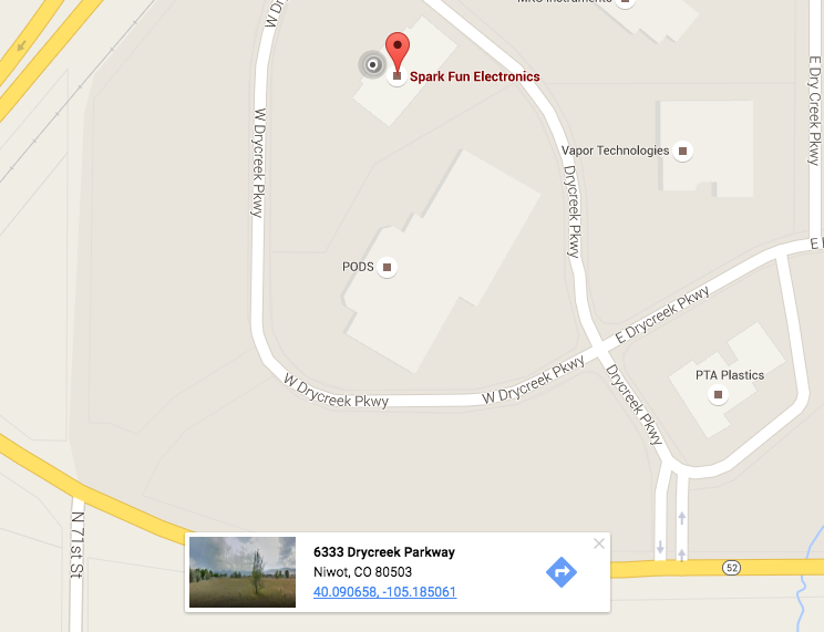
The first thing I needed were the latitude and longitude of the office. Searching for SparkFun in Google Maps shows a red pin on our building. Clicking near the front door, but not on the existing pin dropped a new pin which also made a card appear bottom center. The bottom of this card contains a link to a search of the latitude and longitude marked by the new pin.
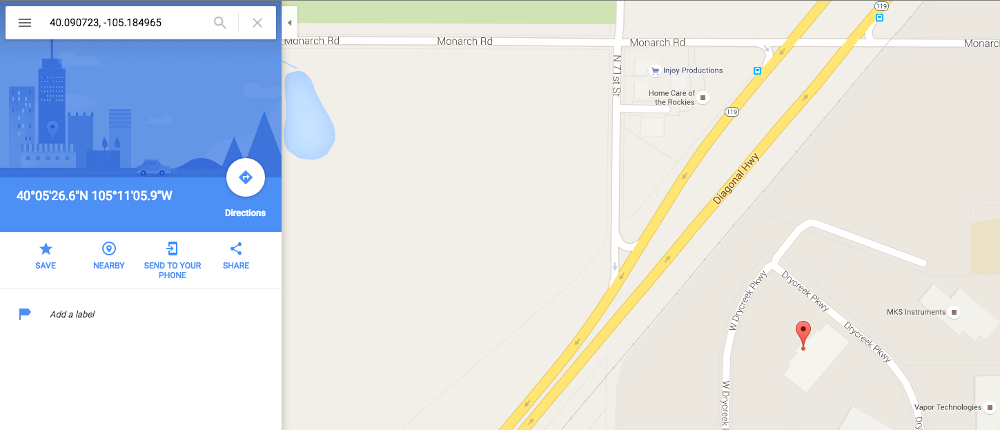
Clicking on the link in the card brings up a page showing the latitude and longitude in both the decimal degrees (DD) and degrees minutes seconds (DMS) forms. I find sign errors easier to avoid by using DMS form Google provides with the since I'm not intimately familiar with the WGS 84 coordinate reference system (CRS). The included cardinal directions are handy and required by the next tool.
The second tool is the default magnetic field calculator on NOAA's website. Enter the coordinates found in the previous step into the latitude and longitude inputs. The Calculate button will trigger a dialog box with the results to appear. If the results appear on the Google map where you are expecting them, then you chose the correct directions with the radio inputs!
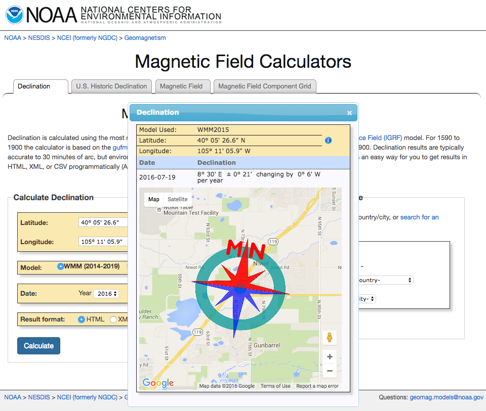
Note that the declination here is currently 8˚ 30' E. Also note that the image on the map shows magnetic north to be east of true north. The provided DM format needs to be converted to DD format for the code. There are 60 minutes per degree, 30 of them is 30⁄60 of a degree, or 0.5˚. The declination in DD format is thus 8.5˚ E. Update the code in the example sketch around line 391 with the declination for your desired location.
language:c
myIMU.yaw   -= 8.5;
What You Should See
The library left a lot of the math in the example sketch in part to make things like this easier to access. Here is an example of what the output of the demo sketch should look like:
language:bash
MPU9250 I AM 71 I should be 71
MPU9250 is online...
x-axis self test: acceleration trim within : 2.4% of factory value
y-axis self test: acceleration trim within : 0.5% of factory value
z-axis self test: acceleration trim within : -0.0% of factory value
x-axis self test: gyration trim within : -0.3% of factory value
y-axis self test: gyration trim within : -1.0% of factory value
z-axis self test: gyration trim within : 0.5% of factory value
MPU9250 initialized for active data mode....
AK8963 I AM 48 I should be 48
AK8963 initialized for active data mode....
X-Axis sensitivity adjustment value 1.21
Y-Axis sensitivity adjustment value 1.22
Z-Axis sensitivity adjustment value 1.17
ax = -70.19 ay = -70.56 az = 931.03 mg
gx = 0.02 gy = 0.00 gz = 0.02 deg/s
mx = -189 my = 355 mz = 127 mG
q0 = 0.97 qx = -0.04 qy = 0.03 qz = 0.22
Yaw, Pitch, Roll: 16.45, 4.22, -4.14
rate = 140.15 Hz