MS5803-14BA Pressure Sensor Hookup Guide
 CaseyTheRobot
Connecting the Hardware - I2C
In this example, we will communicate with the MS5803-14BA using the I2C interface.
Connection Names
The MS5803-14BA Breakout Board breaks out seven connections from the IC. We traditionally call these connections "pins" because they come from the pins on the IC, but they are actually holes that you can solder wires or header pins to.
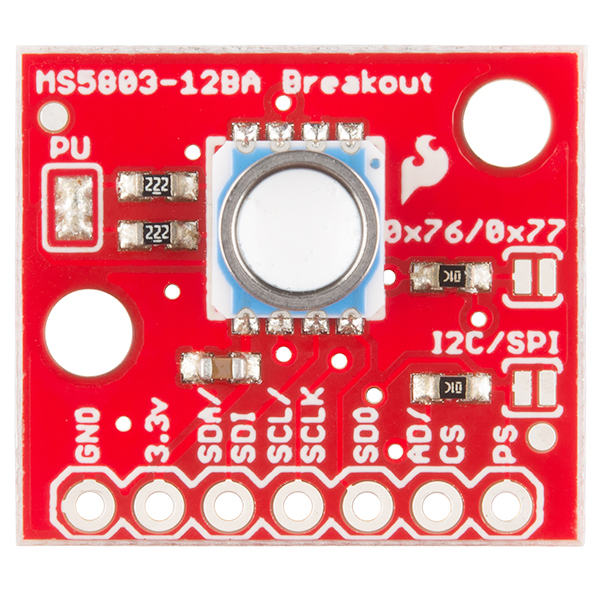
We'll connect four of the seven pins on the board to your Arduino. The four pins you need are labeled GND, VCC, SCL, and SDA.
Connecting Headers to the Board
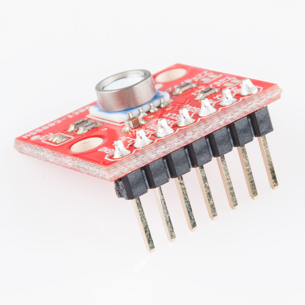
You can use any method you like to make your connections to the board. For this example, we'll solder on a seven-pin length of male-male header strip, and use male-female jumper wires to connect the MS5803-14BA to your Arduino.
Solder a 7-pin length of male-male header to the board. You can solder it to either side. The bottom is more useful for breadboards, and the top is more useful for jumper wires.
Connecting the Board to your Arduino
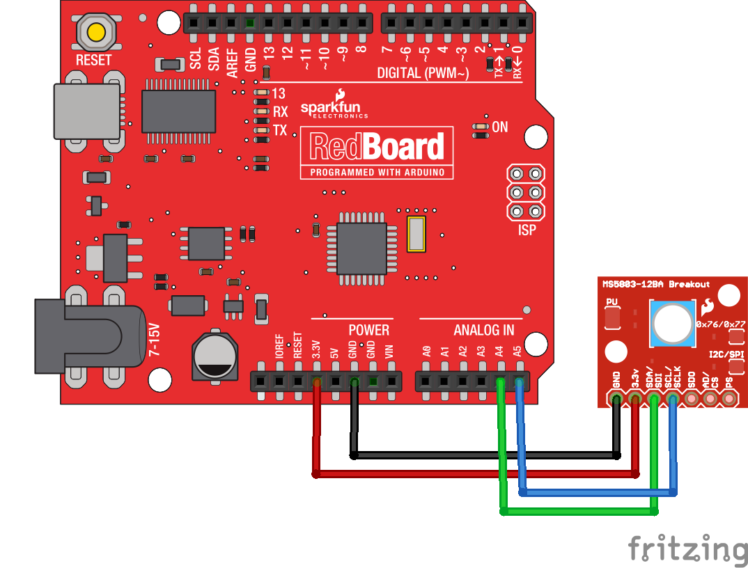
When you're done soldering, connect the GND, 3.3v, SDA, and SCL pins to your Arduino. Different Arduino models use different pins for the I2C interface; use the following chart to determine where to plug everything in.
IMPORTANT: Connect the power pins (3.3v and GND) ONLY to a 3.3V supply. Larger voltages will permanently damage the part. Note that because I2C uses open drain drivers, it is safe to connect the I2C pins (DA and CL) to an I2C port on a 5V microprocessor.
| MS5803-14BA label | Pin function | Arduino connection | ||||||
|---|---|---|---|---|---|---|---|---|
| GND | ground | GND | ||||||
| 3.3v | 3.3V power supply | 3.3V | ||||||
| SDA | I2C data |
Any pin labeled SDA, or:
|
||||||
| SCL | I2C clock |
Any pin labeled SCL, or:
|
Once you have the MS5803-14BA connected to your Arduino, we're ready to play with the software.