OpenLog Artemis Hookup Guide
 Nate
Nate bboyho
 PaulZC
Configuration
Configuring the settings is as easy as opening a serial menu. You can use any serial monitor or terminal emulator to quickly and easily change and store the OLA settings via its USB-C interface.
If you are familiar with the Arduino IDE, you can open the Serial Monitor to configure the OLA.
Serial Terminal Basics
September 9, 2013
If you don’t have the Arduino IDE installed, Don’t Panic!, there are plenty of free alternatives out there:
The above guides will show you how to open the correct port for the OLA and how to set the baud rate to 115200 baud. If you are using the Arduino IDE, set the line ending to Newline. You can change the OLA’s baud rate through the configuration menus too should you need to.
Menu Menu
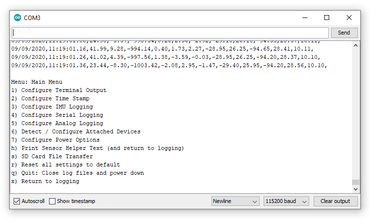
If you have been following along with the tutorial and have inserted a blank microSD card into your OLA and then connected via USB-C, when you open the serial terminal you should see:

The messages in the serial terminal tell us:
- This is the first time the OLA has been powered up and so the default settings are being used
- The OLA software version is V1.6
- Sensor data is being logged to dataLog00000.TXT
- Any incoming serial data on the RX pin will be logged to serialLog00000.TXT
- The microSD card has been found (and is formatted correctly)
- The on-board Inertial Measurement Unit has been found
The columns of data scrolling up the screen are: RTC date, RTC time, IMU accelerometer readings (milli-g), IMU gyro readings, IMU magnetometer readings (nT), IMU temperature (C), the logging rate (Hz).
The logging rate defaults to 10Hz, so as the data scrolls past, you will see the last value settle at 10.00Hz.
Right! Let’s open the main menu by: clicking “Send” if you are using the Arduino IDE; or pressing any key if you are using one of the other serial terminal programs.
The menus will timeout after 15 seconds of inactivity, so if you do not press a key the OLA will return to data logging after 15 seconds.
Let’s start by setting the Real Time Clock (RTC). If you are using the Arduino IDE. enter 2 in the text box at the top of the window and click Send or press the Enter key on your keyboard. If you are using another serial monitor, type 2 followed by Enter. The Time Stamp menu will be displayed:
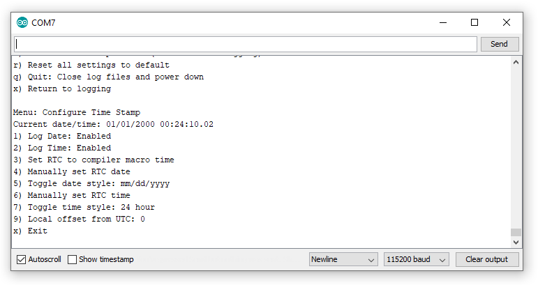
Time Stamp Menu
Let’s use option 4 to set the RTC date. Type 4 followed by Send or Enter. The menu asks us for the two digit year, followed by the month and day:
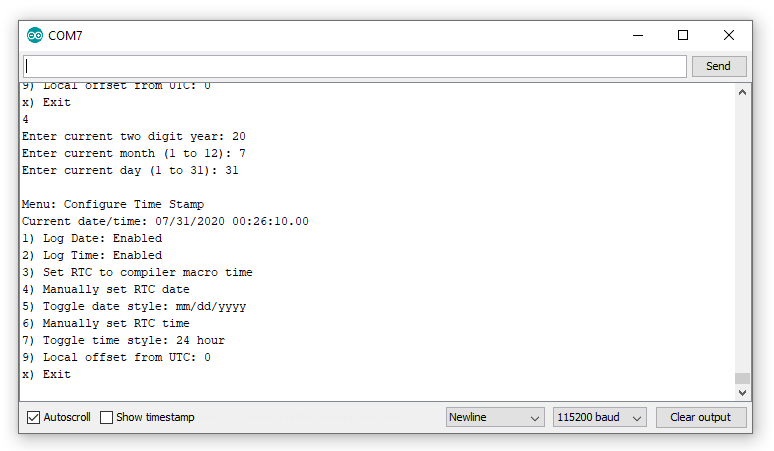
The menu now shows that we have set the date and that the MM/DD/YYYY style is being used. We can swap to DD/MM/YYYY by using option 5:
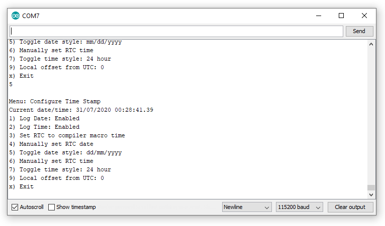
Now we can use option 6 to set the time:
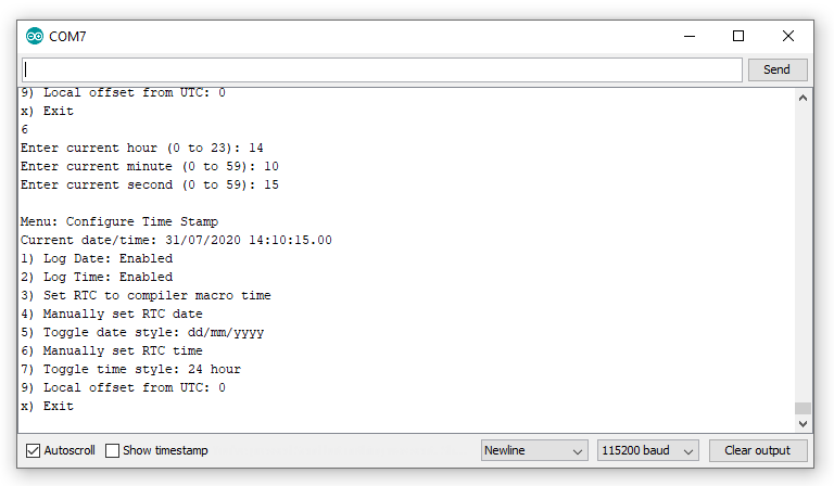
We need to enter the hour in 24 hour format even if 12 hour format has been selected (using option 7).
To set the clock accurately, you can enter a value for the seconds that is a few seconds ahead of time and then hit Enter or click Send when your watch reaches that second.
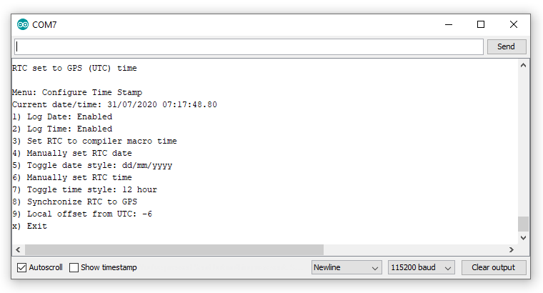
If you have a u-blox Global Navigation Satellite System (GNSS) module attached, you will see an extra option “8” which allows you to set the time to Universal Time Coordinate (UTC) using GNSS. You can use option 9 to set your local time offset. Do this before you use option 8. E.g. if you are in Colorado and daylight saving is in effect, enter -6 as the offset. Mountain Time is 6 hours behind UTC in summer.
Options 1 and 2 can be used to stop the OLA from logging the time and date should you want to.
Press x followed by Enter or Send to return to the main menu, or wait 15 seconds for the menu to timeout.
The RTC back-up battery will keep the RTC running while the OLA is in deep sleep. (Don’t forget: pressing the RST button with no power source connected will cause the RTC to reset.)
Main Menu (Part 2)
There are some other important options on the menu menu that we should cover, before we move on to the other menus:
Use option h to print the log data helper text (and return to logging) if you need a reminder of what each column of data is.
As of firmware v1.6, option s will open the SD Card File Transfer menu. See “SD Card File Transfer” for more details.
Option r followed by y will reset all of the OLA’s settings back to the default both in EEPROM and on SD card.
Option q followed by y is a clean way to stop the OLA from logging. The OLA will close the log files on the SD card, making sure the contents are saved, and will then go into deep sleep to minimize current draw. Once in deep sleep, the Artemis needs to be reset to wake it up again. You can do this by:
- Pressing the RST button
- Pressing an external reset button which is wired to the RST and GND breakout pins
- Closing and opening the serial terminal. Re-opening the serial terminal generates a reset to via the bootloader circuit.
Option x will exit the menu and the OLA will return to data logging.
Configure Terminal Output
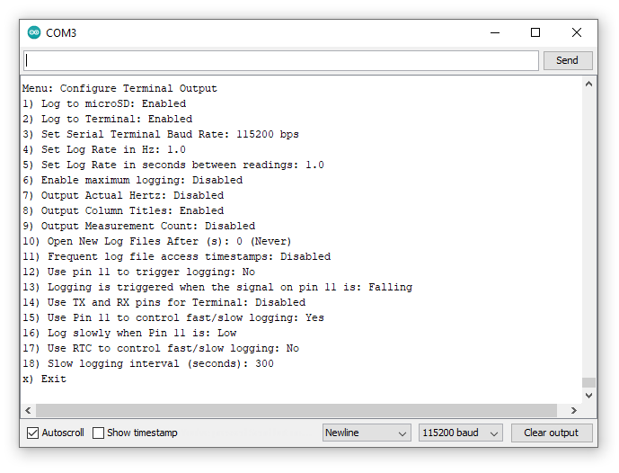
Option 1 from the main menu will open the menu to configure the terminal output:
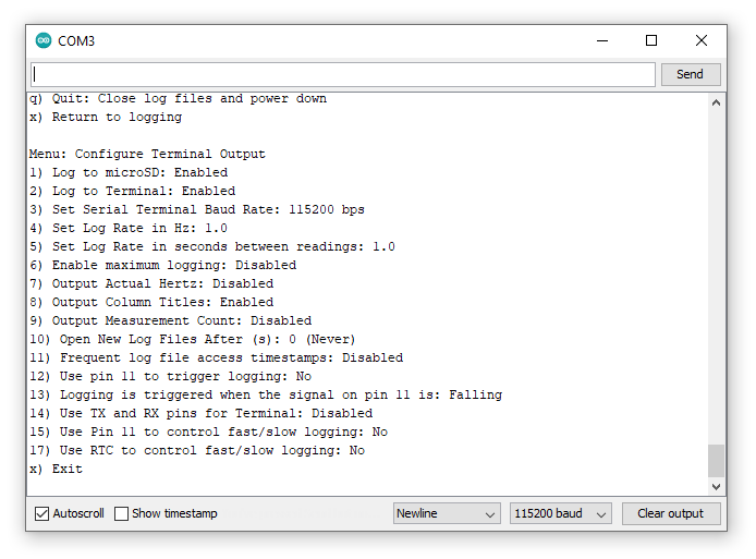
Option 1 can be used to enable or disable microSD card logging. If you are not logging to SD card, data can still be displayed on the terminal as normal.
Option 2 can be used to disable data display in the terminal. Setting “Log to Terminal” to “Disabled” stops the data from being displayed in the terminal, but it will still be logged to SD card if “Log to microSD” is enabled.
Option 3 can be used to change the baud rate used by the terminal. You will need to close and reopen the serial monitor / terminal at the new baud rate if you change this. Note: serial RX and TX pins have their own baud rate - set via main menu option 4: “Configure Serial Logging”.
Options 4 and 5 can be used to set the log rate. The log rate defaults to 10Hz. If you want to log quickly, use option 4 to set the log rate in Hz (samples per second). For slow logging, more than 1 second between samples, use option 5. The log rate sets the maximum rate for data logging, the actual log rate may be slower than this depending on what sensors are connected.
Option 6 tells the OLA to log data as fast as possible. The maximum rate depends on the number of sensors connected to the OLA.
Option 7 can be used to enable or disable logging of the actual logging rate. If you’re trying to be economical with your data, then you may wish to disable this, however leaving it enabled is a useful way to tell what logging rate was achieved.
Option 8 can be used to prevent the data column helper text from being written to the log files. If you want the log file to contain purely data, you may wish to disable this option.
Option 9 can be used to add a measurement count to each data sample. The measurement count is incremented after each sample.
Option 10 can be used to make the OLA open a new log file after the specified number of seconds. There is a small risk of data loss if the OLA’s power is removed while data is being written to the SD card. By telling the OLA to open a new log file say every hour (3600 seconds) then the most data you can lose is the past hour. (Connecting a stop logging button can prevent data loss too. See “Low Power Considerations” for further details.)
As of firmware v1.6, the following options are available:
Option 11 can be used to enable frequent log file timestamps. As of firmware v1.6, the log file create and access timestamps (metadata) are correctly set by the OLA’s Real Time Clock. By default, the access timestamps are only updated when the log files are closed. You can use option 11 to make the OLA update the timestamps frequently. However, doing so causes more SD card writes which can cause problems when logging at high rates. We made this option configurable so you can decide which is best for your application.
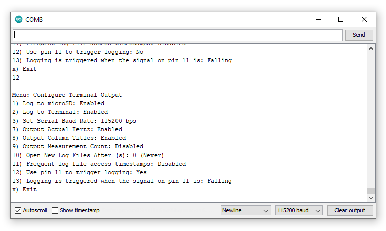
Option 12 allows pin 11 to be used to trigger sensor logging. When triggering is enabled, the sensor data is logged on every rising or falling edge on pin 11 (configurable via option 13). The normal log rate settings (options 4-6) are ignored while triggering is enabled and disappear from the menu:
As of firmware 1.9, you can use option 14 to use the TX and RX pins for the serial terminal / console. This option will allow you to attach a Bluetooth or radio modem to the OLA and access your data that way, instead of needing to use USB. You can change the Baud rate using option 3. You can still use USB when this option is enabled - you can use USB and TX/RX simultaneously. It is fun to have the TX/RX and USB serial monitor windows open at the same time, watching them both do the same thing as you type into one or the other! ZMODEM file transfer via TX/RX is supported too. Selecting this option will of course disable analog logging on the TX/RX pins and will disable serial logging too.
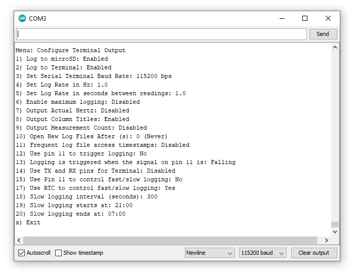
As of firmware 1.9, you can use option 15 to make Pin 11 control when the OLA goes into slow logging mode. Slow logging will help conserve your battery life. Let's say you only want to log during daylight hours. You could connect a 3.3V daylight sensor signal to Pin 11 so you only log at normal speed during the day and slowly at night. You can set the polarity of Pin 11 using option 16. You can set the slow rate for night using option 18.
As of firmware 1.9, you can use option 17 to go into slow logging mode once per day. Again, let's suppose you want to log at normal speed during the day and then log slowly during the night. Option 17 let's you do that. You can use options 19 and 20 to set the times when slow logging should start and end.
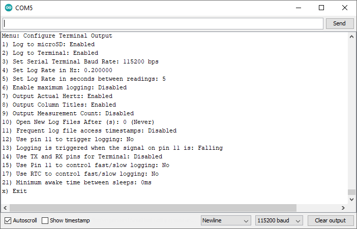
As of firmware v1.11, you can now specify a minimum awake time for those occasions when the logging interval is greater than two seconds and the OLA goes into deep sleep between measurements. Previously it was difficult to re-open the serial menus, you had to keep hitting a key at the right moment to open the menu and stop the OLA from going back to sleep. You can now use option 21 to set a minimum awake time, in milliseconds. The OLA will wake from deep sleep, take a measurement, log it to the microSD card, optionally transmit it via the TX pin, and then remain awake for the required time, giving you time to open the serial menu. Leave this option set to zero if you want the OLA to go immediately back to sleep.
Configure IMU Logging
Option 3 from the main menu will open the menu to configure Inertial Measurement Unit logging:
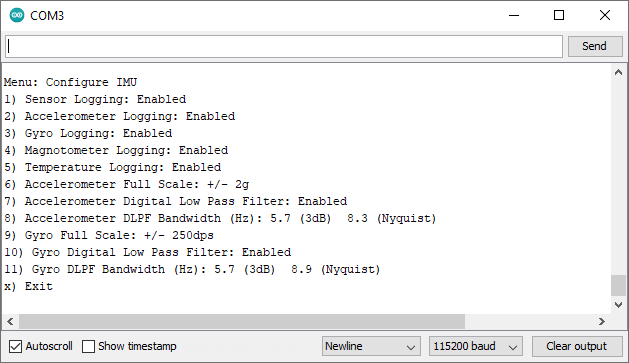
If you want to disable IMU logging completely, you can do this using option 1 to set sensor logging to disabled.
Options 2, 3, 4 and 5 can be used to selectively enable or disable logging of the accelerometer, gyro, magnetometer and temperature readings. If you just want to log temperature, use 2, 3 and 4 to disable the other readings.
As of firmware v1.7, you can use options 6 to 11 to configure the accelerometer and gyro full scale values, enable/disable the Digital Low Pass Filters, and define the DLPF bandwidths.
As of firmware v1.11, you can now optionally log quaternion orientation data using the ICM-20948 Digital Motion Processor™. For further details, please see the DMP documentation in the ICM-20948 library. Option 12 enables support for the DMP.
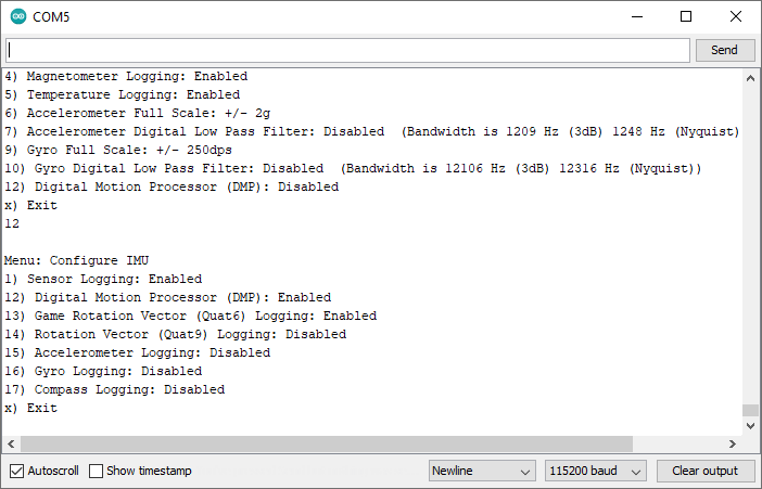
Once the DMP is enabled, you can select six-axis quaternion (Quat6) or nine-axis quaternion (Quat9) data for logging, plus the raw accelerometer, gyro and compass data. Quat6 only makes use of the accelerometer and gyro data. Quat9 includes the magnetometer (compass) data and provides absolute orientation with respect to magnetic North.
The quaternions Q1-Q3 are logged to SD card. You can manually calculate Q0 and the Euler angles (roll, pitch and yaw) from the logged data. There is a new stand-alone example called IMU_DMP_Quat6 in the GitHub repo which shows how to do that.
Please note that the DMP requires calibration. You will need to slowly rotate the OLA around all three axes and hold it stationary for a few seconds in all six orientations before the Quat9 data becomes well behaved.
Configure Serial Logging
Option 4 from the main menu will open the menu to configure serial logging:
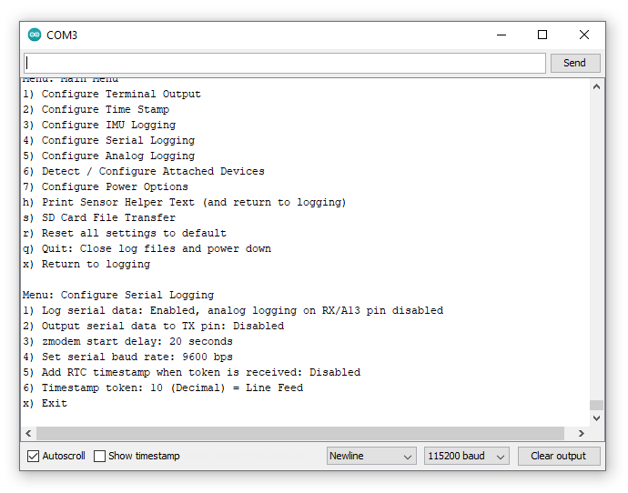
Serial logging on the RX pin (13) is enabled by default and the OLA is expecting data at 9600 baud (bits per second).
You can disable or re-enable serial logging using option 1.
As of firmware v1.6, option 2 can be used to enable or disable streaming of the sensor data to the serial TX pin. Serial data is transmitted using the same CSV format as the data which is logged to SD card or displayed on the terminal.
Option 3 can be used to set the start delay for ZMODEM file transfers through the SD Card File Transfer menu. See “SD Card File Transfer” for details.
Option 4 can be used to change the serial logging baud rate. Most older GNSS modules output data at 9600 baud, but the newer ones use 38400 baud. Any valid baud rate up to 500000 [1] can be used.
As of firmware 1.9, option 5 will allow you to add timestamps to your serial log file. When enabled, a timestamp will be added whenever the timestamp token is received. You can use option 6 to change the value of the token. Common values will be 10 (Line Feed), 13 (Carriage Return) or maybe 27 (Escape). You can select any value from 0 to 255. Options 1, 2 and 10 in the Time Stamp Menu control if the date, time and/or microseconds are added.
Configure Analog Logging
Option 5 from the main menu will open the menu to configure analog logging:
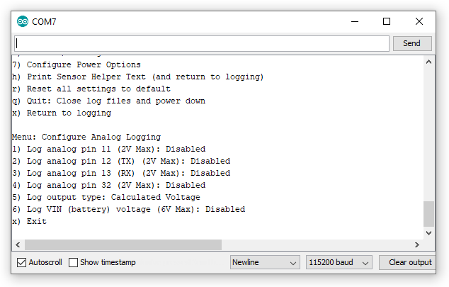
All four breakout pins (32, TX, RX and 11) can be used to log analog voltages up to a maximum of 2.0V. Analog logging is disabled by default but can be enabled with options 1, 2, 3 and 4.
Please be aware that analog logging and some of the OLA’s other logging features are mutually-exclusive:
- If you enable analog logging on pin 32, stop logging functionality is automatically disabled
- If you enable analog logging on pin 12 (TX), serial data output is automatically disabled
- If you enable analog logging on pin 13 (RX), serial logging is automatically disabled
- If you enable analog logging on pin 11, triggering is automatically disabled
Option 5 can be used to toggle between logging voltages (0.0V to 2.0V) and raw Analog to Digital Converter (ADC) units (0 to 16383).
Option 6 can be used to enable logging of the battery / bus voltage VIN. This is a useful way to log how quickly your battery discharges. Please note that this option is not supported on the older SparkX version of the OLA.
Configure Attached Devices
Option 6 from the main menu will open a menu which allows you to configure the settings for all devices attached to the Qwiic bus. For example, if you have an MS8607 PHT sensor, LPS25HB pressure sensor and an SHTC3 humidity sensor attached to the OLA, the menu will look like this:
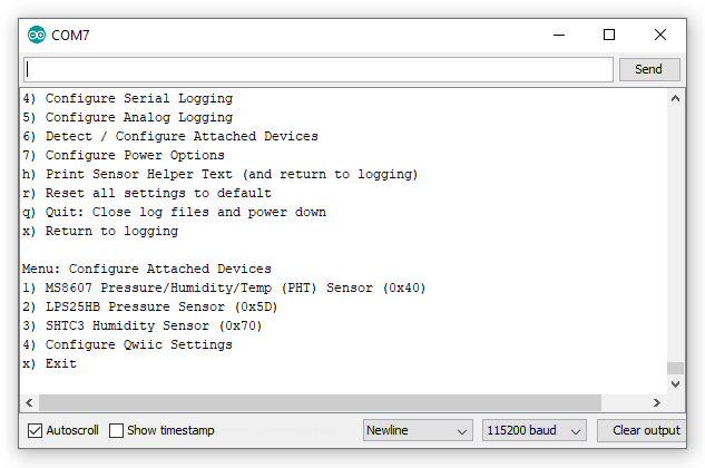
Just like for the built-in IMU sensor (if it is populated), if you open any of the menus you will be presented with a set of options where you can enable/disable logging from that sensor completely, or select which sensor values to log:
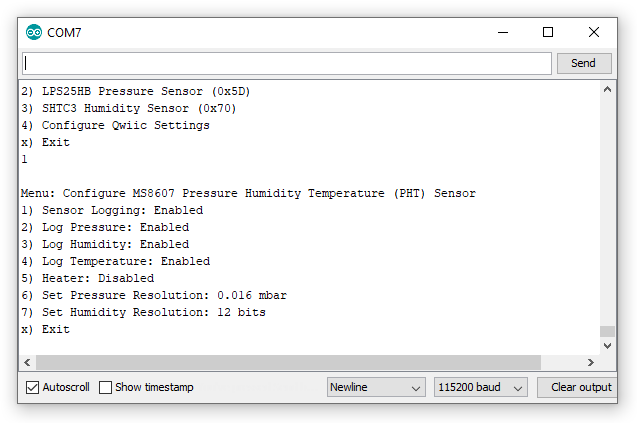
If the sensor has any configurable settings, those will be shown too.
There is an option on the devices menu which allows you to configure options for the Qwiic bus itself:
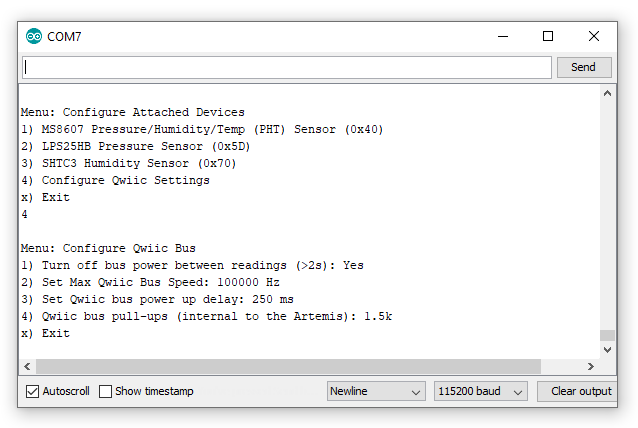
If you are using long logging intervals, set through the Configure Terminal Output menu, you can choose to completely turn off any sensors attached to the Qwiic bus while the Artemis is sleeping between readings. Use option 1 to toggle this setting. Please be aware that some sensors do not enjoy being turned off. GNSS sensors in particular need time to establish a fix even if they are performing a “hot start”. You can counteract this by setting a longer power up delay using Option 3.
Option 2 allows you to set the maximum speed for the Qwiic I2C bus. Valid values are 100000 and 400000 Hz. Please note that some sensors can only operate at lower bus speeds. The value you enter here is the maximum speed that will be used and may be ignored depending on what sensors are connected.
Option 3 allows you to adjust the delay between turning on the Qwiic bus power and logging being (re)started. Some sensors require more time than others to begin operation after the power is reconnected; this option sets the minimum time the OLA will wait before attempting to communicate with the Qwiic devices. If you have a ‘slow’ device like the SCD30 attached, the power up delay is automatically extended to 5 seconds. If you have a u-blox GNSS module attached and you want to give it time to establish a fix before the position data is read, you can extend the power up delay to a maximum of 60 seconds.
Option 4 is for advanced use and allows you to specify the value of the I2C pull-up resistors internal to the Artemis. For sensors like the u-blox GNSS modules, it is beneficial to disable the pull-ups completely by setting the value to zero. The other possible values are: 1.5k, 6k, 12k and 24k.
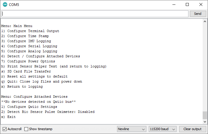
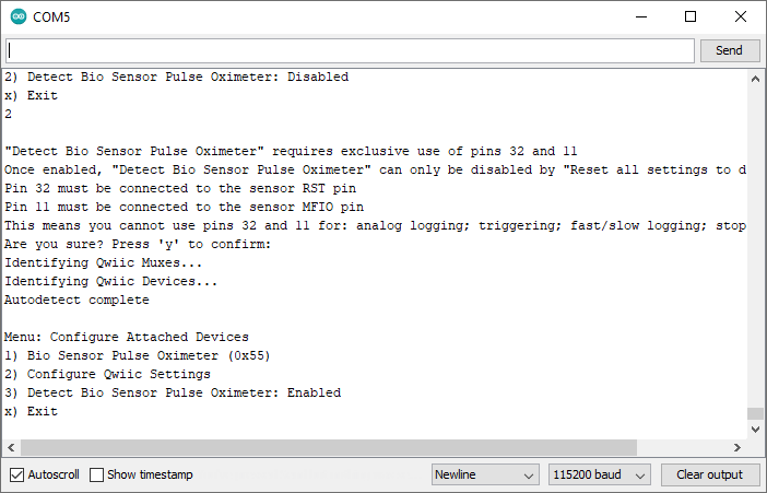
As of firmware v1.11, the OLA supports data logging from the MAX30101 Pulse Oximeter and Heart Rate Sensor .The Oximeter has two breakout pins, RST and MFIO, which need to be connected to Pin 32 and Pin 11 on the OLA. Because the Oximeter needs exclusive access to these pins, you need to enable detection of the Oximeter through this menu.
Enabling Oximeter detection means that you cannot use pins 32 and 11 for their other functions (analog logging, stop logging, triggering, fast/slow logging). You will see a warning message asking you to confirm that you want to proceed:
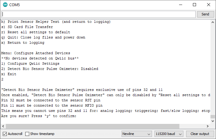
After pressing "y", the Oximeter will be detected and you can configure it in the same way as any other Qwiic sensor.
Configure Power Options
Option 7 from the main menu will open the menu to configure the power options:
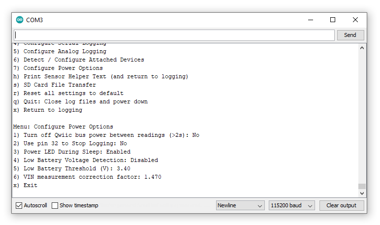
Option 1 is a repeat of the bus power option on the Configure Qwiic Bus menu. It allows you to disable power to the Qwiic bus completely while the OLA is asleep.
Breakout pin 32 can be used to make the OLA stop logging, close the SD log files safely and go into deep sleep. This feature can be enabled using option 2. If this option is enabled, pulling pin 32 to GND will stop the OLA logging. Please note that enabling this feature will prevent analog logging on pin 32. Please see “Low Power Considerations” for further details.
For low power applications, the PWR LED can be turned off while the OLA is asleep between readings. This setting can be toggled using option 3. Please note that this option is not supported on the older SparkX version of the OLA.
As of firmware v1.6, option 4 can be used to enable or disable low battery detection. The low battery threshold voltage can be set using option 5. When low battery detection is enabled, the OLA will automatically stop logging and go into deep sleep when the battery voltage falls below the threshold.
The OLA uses a high impedance two resistor divider to measure the VIN battery / bus voltage. This requires a correction factor to convert the reading into the true voltage. You may need to change this value to compensate for the actual resistor values on your OLA. If you select option 6 you will be asked to measure and enter the true voltage between the MEAS pin and GND. You will need a multimeter to measure the voltage. The correction factor will be adjusted according to the value you enter. Please note that this option is not supported on the older SparkX version of the OLA.

SD Card File Transfer
As of firmware v1.6, the SD Card File Transfer menu can be used to access the files on the SD card:
As of firmware v1.9, you can also transfer files via the TX and RX pins. Please see option 14 in the Configure Terminal Output menu. Note: you can only have the SD Card File Transfer menu open on either USB or TX/RX. (You cannot have it open on both at the same time.)
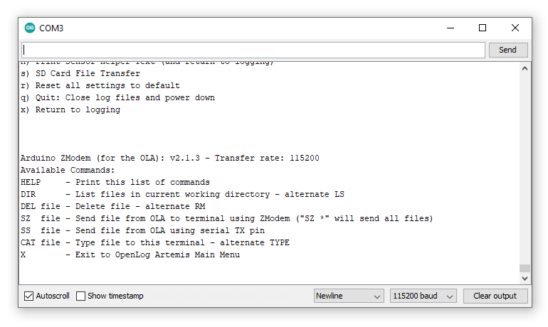
When the SD Card File Transfer menu is open, the OLA will respond to a number of commands:
- help will redisplay the menu help
- dir or ls will list all of the files on the SD card, together with their access timestamps (metadata) and sizes
- del filename or rm filename will delete an individual file
- cat filename or type filename will type the contents of a file to the terminal
- ss filename will send / copy the chosen file to the serial TX pin. You can set the baud rate using the Configure Serial Logging menu
- sz filename will start a file transfer using the ZMODEM protocol (see below)
- sz * will transfer all of the files on the SD card using ZMODEM
- x will return to the main menu. Note that the normal 15 second menu timeout does not apply to the SD Card menu, you do need to type x to return
The ZMODEM file transfer protocol has been around since 1986 and allows files to be transferred between terminal emulators. The Tera Term terminal emulator still supports ZMODEM. You will find the file-receive option in the File > Transfer menu:
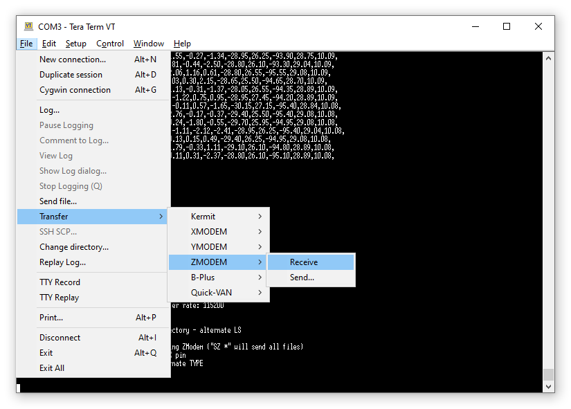
With the SD Card menu open, you can start a file transfer by typing sz followed by the filename into Tera Term:
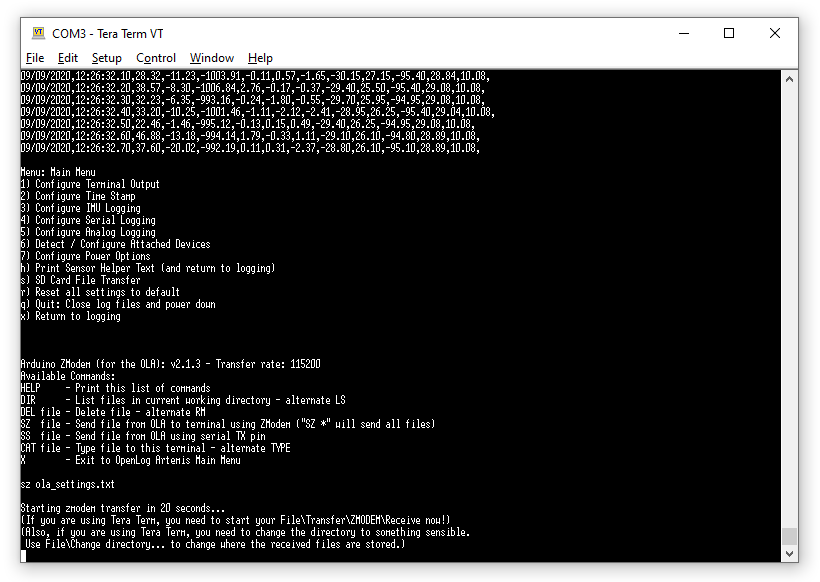
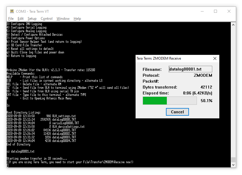
Start the ZMODEM receive in Tera Term and, after 20 seconds, the transfer will take place:
You may also want to use the File > Change directory… option in Tera Term to change the directory where the received files are stored.