OpenLog Hookup Guide
 Nate
Nate Toni_K
Hardware Hookup
There are two main methods for connecting your OpenLog to a circuit. You will need some headers or wires to connect. Make sure that you solder to the board for a secure connection.
Basic Serial Connection


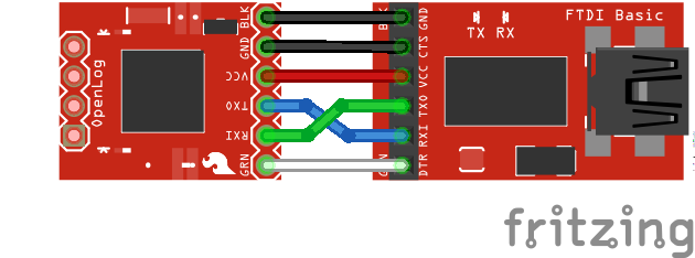
This hardware connection is designed for interfacing with an OpenLog if you need to reprogram the board, or log data over a basic serial connection.
Make the following connections:
OpenLog → 3.3V FTDI Basic Breakout
- GND → GND
- GND → GND
- VCC → 3.3V
- TXO → RXI
- RXI → TXO
- DTR → DTR
Notice that it is not a direct connection between the FTDI and OpenLog - you must switch the TXO and RXI pin connections.
Your connections should look like the following:
Once you have the connections between the OpenLog and the FTDI Basic, plug your FTDI board into a USB cable and into your computer.
Open up a serial terminal, connect to the COM port of your FTDI Basic, and go to town!
Project Hardware Connection


While interfacing with the OpenLog over a serial connection is important for reprogramming or debugging, the place where OpenLog shines is in an embedded project. This general circuit is how we recommend you hook up your OpenLog to a microcontroller (in this case, an Arduino Pro Mini) that will write serial data out to the OpenLog.
First you will need to upload the code to your Pro Mini you intend to run. Please check out the Arduino Sketches for some example code that you can use.
Using the Arduino Pro Mini 3.3V
Once you have programmed your Pro Mini, you can remove the FTDI board, and replace it with the OpenLog. Make sure to connect the pins labeled BLK on both the Pro Mini and OpenLog (the pins labeled GRN on both will also match up if done correctly).
If you cannot plug the OpenLog directly into the Pro Mini (due to mismatched headers or other boards in the way), you can use jumper wires and make the following connections.
OpenLog → Arduino Pro/Arduino Pro Mini
- GND → GND
- GND → GND
- VCC → VCC
- TXO → RXI
- RXI → TXO
- DTR → DTR
Once you're finished, your connections should look like the following with the Arduino Pro Mini and Arduino Pro. The Fritzing diagram shows the OpenLogs with the headers mirrored. If you flip the microSD socket relative to the Arduino's top view, they should match the programming header like an FTDI.
 |
 |
Power up your system, and you are ready to start logging!