OpenPIR Hookup Guide
 jimblom,
  SFUptownMaker
Hardware Overview
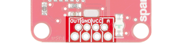
Powering and interfacing with the OpenPIR is accomplished using the four pins broken out on the bottom of the board. Those pins are:
| Pin Label | Description |
|---|---|
| A | Analog output of NCS36000 differential amplifiers. |
| VCC | Power supply input |
| GND | Ground supply input |
| OUT | Digital output signal – active-high. |
More on those pins in the sections below.
Supplying Power
Power to the OpenPIR should be supplied to the VCC and GND pins. The OpenPIR's operating voltage supply range is 3V to 5.75V --- as specified by the board's NCS36000 PIR controller. That means it should work with any 3.3V or 5V system.
Electrical characteristics:
- Voltage supply range: 3VDC to 5.75VDC
- Standby average current: 80µA
- Motion-detected average current: 3mA (LED enabled)
The OpenPIR consumes relatively little power. When the sensor isn't triggered --- and the activity LED is not illuminated --- the OpenPIR will consume about 80µA. When active, the onboard LED's current draw dwarfs the PIR's operating current, consuming about 3mA. That LED can be disabled using the xLED jumper (see applicable section below).
Digital Motion Trigger Output
The OUT pin is an active-high digital signal, which indicates the OpenPIR's motion detection. When motion is detected, the pin is driven HIGH; otherwise it will be LOW.
This pin can drive up to 10mA --- so you can hook an LED or other small load up to it. Otherwise it can be connected directly to a microcontroller input pin (no pull-up or pull-down resistor required).
The operation of this pin is mirrored by the green, reverse-entry "DET"-labeled LED --- if the LED is on, the OUT pin should be HIGH.
The duration of a HIGH signal on the OUT pin is set by the "OSC" trimpot, which is discussed more in-depth later in this section.
Analog Output
The "A"-labeled output breaks out the amplified PIR signal before it's sent to a window comparator, and then to the OUT pin.
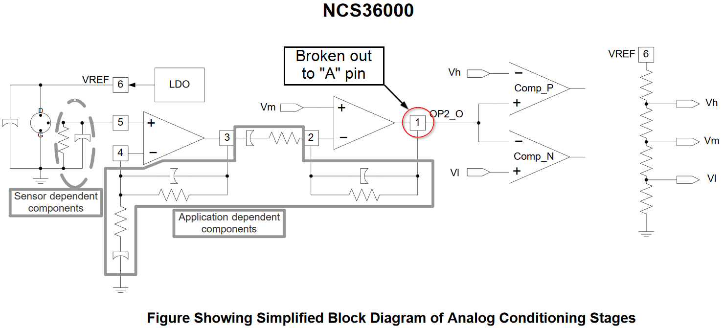
Absent of any motion, the voltage at this pin will hover around 2.1V (about 430 on a 5V Arduino's 10-bit ADC input). As motion is detected, though, that voltage may swing wildly.
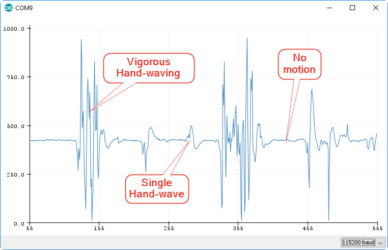
This pin can be used to get a better idea of what kind of motion triggered the PIR. Single passes by the PIR may only produce a small "blip" on the "A" pin, while vigorous motion may produce a large, spiky wave output.
LED Output
A reverse-entry green LED is included on the board, which duplicates the status of the OUT pin. When motion is detected, the LED will illuminate; otherwise it will remain off.

On initial power-up, the LED will blink, indicating the NCS36000 is in start-up mode. Start-up mode can last for a few seconds or a couple of minutes --- the length of time spent in start-up depends on the position of the "OSC" trimpot. The start-up mode time upon shipment is about two minutes.
The LED can be disabled by opening the "xLED" jumper. Note that the LED will still blink during start-up mode, regardless of the jumper's state.
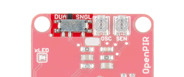
Trimpots --- Sensitivity and Oscillator Window
The pair of trimming potentiometers (trimpots) on the backside of the OpenPIR can be used to customize the behavior of your motion sensor.
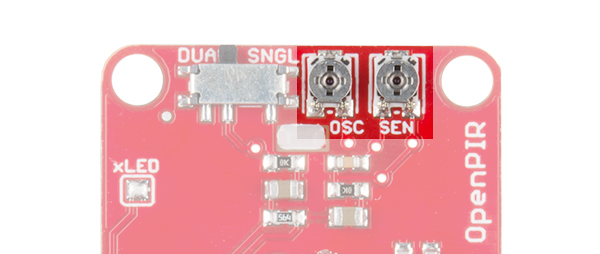
The sensitivity trimpot --- labeled "SEN" --- can be used to adjust the view distance of the OpenPIR. The more clockwise you turn this trimpot, the further your sensor should be able to see. When you receive the board, the trimpot will be centered, and the sensor will react to a person moving about in the 6 to 8 foot (2 to 2.5m) range. At the maximum sensitivity, the sensor will detect a person walking by at about 16 feet (5m).
Avoid turning the "SEN" trimpot all the way down (counter-clockwise). This will disable the OpenPIR's output – even the most mobile environments will not trigger an active output.
The "OSC" trimpot ultimately controls the length of time the output remains HIGH. This trimpot is used to adjust the oscillator frequency of the NCS36000. Turning this trimpot clockwise increases the length of time OUT remains high.
With the OSC trimpot cranked all the way in the counterclockwise direction, the OUT pin will remain HIGH for about 400 milliseconds. Conversely, when the trimpot is turned to the far-clockwise, the OSC pin will remain HIGH for about 7.5 seconds. The trigger time should adjust relatively linearly between those two values. When you receive the board, it will be centered, and the trigger pulse will last a bit less than four seconds.
Trigger Mode --- Dual vs. Single
The NCS36000 supports two motion-detection modes: single-pulse and dual-pulse. Either of these modes can be selected using the switch adjacent to the trimpots on the back of the board.
The NCS36000 uses a window comparator --- a pair of comparators with upper and lower voltage limits --- to trigger a pulse on the OUT pin. In single-pulse mode, a voltage above or below the upper or lower comparators will trigger an output pulse. But in dual-pulse mode, the voltage must swing above the high comparator voltage and below the low comparator voltage --- within a set time limit --- to trigger an output.
These timing diagrams from the NCS36000 datasheet can help to clarify single-pulse versus dual-pulse:
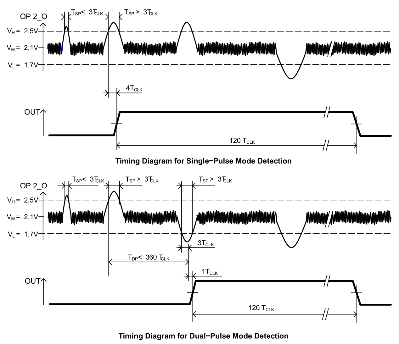
Single-pulse mode can be used to detect an object entering or exiting the PIR's field-of-view, while dual-pulse detection can be used to detect an object entering and leaving the view area.