PCA9306 Logic Level Translator Hookup Guide (v2)
 Toni_K
 bboyho
Hardware Overview
Power and I2C Sides
At a minimum, the breakout board has seven pins that need to be connected to function properly. VREF1, SCL1, and SDA1 all connect to your lower voltage side.
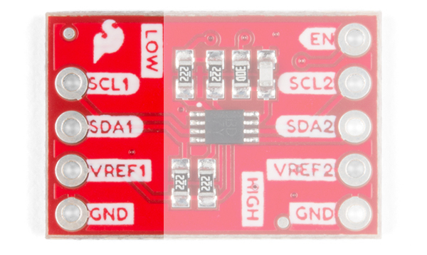
VREF2, SCL2, and SDA2 connect to your higher voltage side. One of the GND pins on either side needs to be connected to ground in your system.
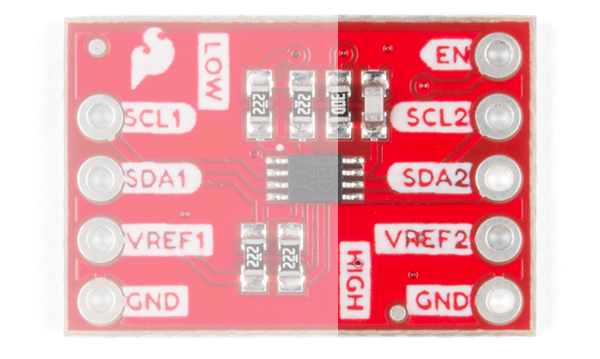
What's that extra through-hole on the board labeled as EN? Well, it can be connected to an I/O pin to toggle the PC9306 from the high side. You'll need to adjust the jumper in the back to be able to use this feature. Check below for more information.
Allowable Voltage Level Translation
For most of the products listed in the catalog, usually you will be translating voltages between 3.3V and 5V. However, the datasheet for the PCA9306 states that it can be used to translate lower voltages if you need. Below are the acceptable voltages on the low and high sides.
| VREF1 (i.e. Low Side) | VREF2 (i.e. High Side) |
|---|---|
| 1.2V | 1.8, 2.5V, 3.3V, 5V |
| 1.8V | 2.5V, 3.3V, 5V |
| 2.5V | 3.3V, 5V |
| 3.3V | 5V |
Jumpers
There is a jumpers on the underside of this board to turn on and off the PCA9306. By cutting the trace and adding a solder jumper toward the pad labeled as "Switch," you can toggle the logic level translator with your microcontroller.
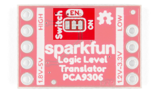
Enable Feature
It's possible to use the PCA9306 as an I²C switch. First, as mentioned above, you'll want to cut the ON trace and solder the Switch trace. To use the feature you'll attach the high side VREF2 to you're high side voltage as you normally would, and then attach the EN (enable) pin, to a digital Pin. Now when you want to enable I²C communication, pull the line HIGH.