pcDuino Hookup Guide
This Tutorial is Retired!
This tutorial covers concepts or technologies that are no longer current. It's still here for you to read and enjoy, but may not be as useful as our newest tutorials.
Contributors:
 SFUptownMaker
SFUptownMaker 
Hardware Tour
Here's a brief visual rundown of the hardware on the pcDuino.
Top side
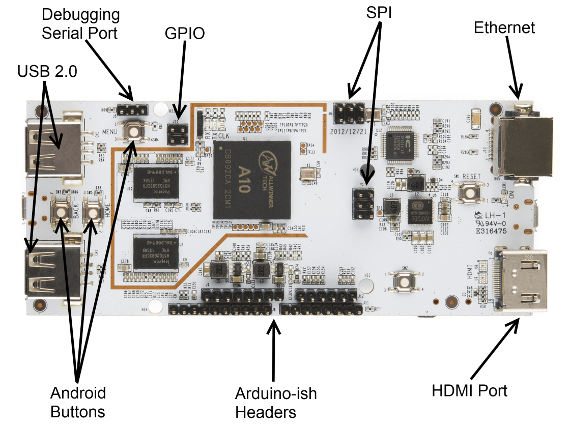
- Debugging serial port - a root-level session is initiated to this serial port at power up. It can be accessed as a 3.3V serial port, 8-N-1, no handshaking. For more information, see this page.
- Android buttons - these duplicate the functions of the hardware buttons on many Android-based tablets and phones. In Android programming, these buttons have a special function.
- GPIO - four 3.3V GPIO pins.
- SPI - two dedicated SPI peripheral headers. J6 is the SPI2 peripheral; J7 is the SPI0 peripheral, which is also broken out to the appropriate pins on the Arduino-ish headers. SPI0 pins also provide access to two more UARTs and external interrupts, as well.
- Arduino-ish headers - these pins closely follow the functionality of the pins on standard Arduino-compatible boards: I2C, SPI, UART, PWM, and ADC. The mapping is the same as it would be on a standard Arduino-compatible, as well, making it easy to convert Arduino shields to work with pcDuino.
Bottom side
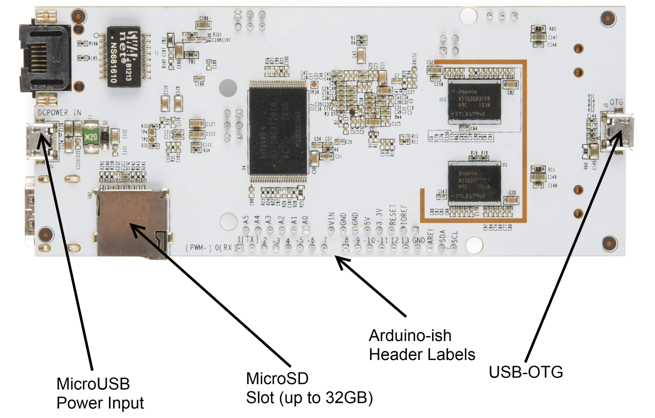
- MicroUSB power port - this port is for power only- the data pins don't connect to anything. The board uses about 500mA under normal circumstances, meaning it can be powered from most USB ports; most modern cellular phone chargers use microUSB as well, making finding a power supply easy.
- USB-OTG port - this port can be used either as a standard USB port (with the appropriate converter) or to connect the pcDuino to another PC for debugging and upgrading the onboard software. The board can be powered through this port for debugging.