Photon Remote Temperature Sensor
 jenfoxbot
 Build It
Let's begin assembling our circuit.
Set up the Particle Photon.
Go to the Photon set up page and follow the instructions to set up your Photon for WiFi. The Photon LED will slowly pulse (aka breathe) light blue (cyan) when it is successfully connected to WiFi. Run through a practice program to check that the Photon is working as expected. The classic Blink sketch is always a good choice.
To program the Photon, we used the Particle Build Web IDE (Integrated Development Environment). Visit the Particle website to guide you through this process.
Locate your specific Photon "Device ID" and the "Access Token". Store in a convenient, and secure, location.
The device ID can be found in Particle Build by clicking the '>' next to your device name.
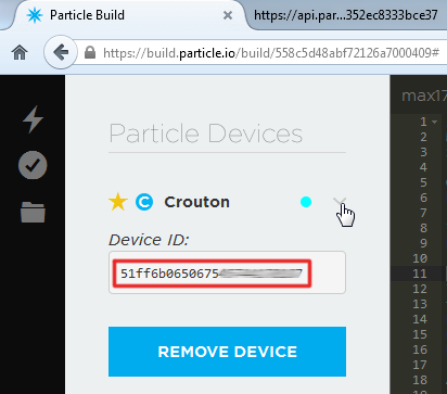
_Find your Device ID under the "Devices" tab, by clicking the carrot next to your Photon._ Your access token can be found under the "Settings" tab.
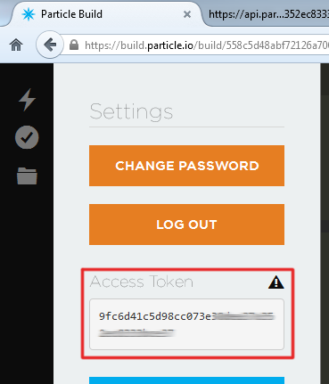
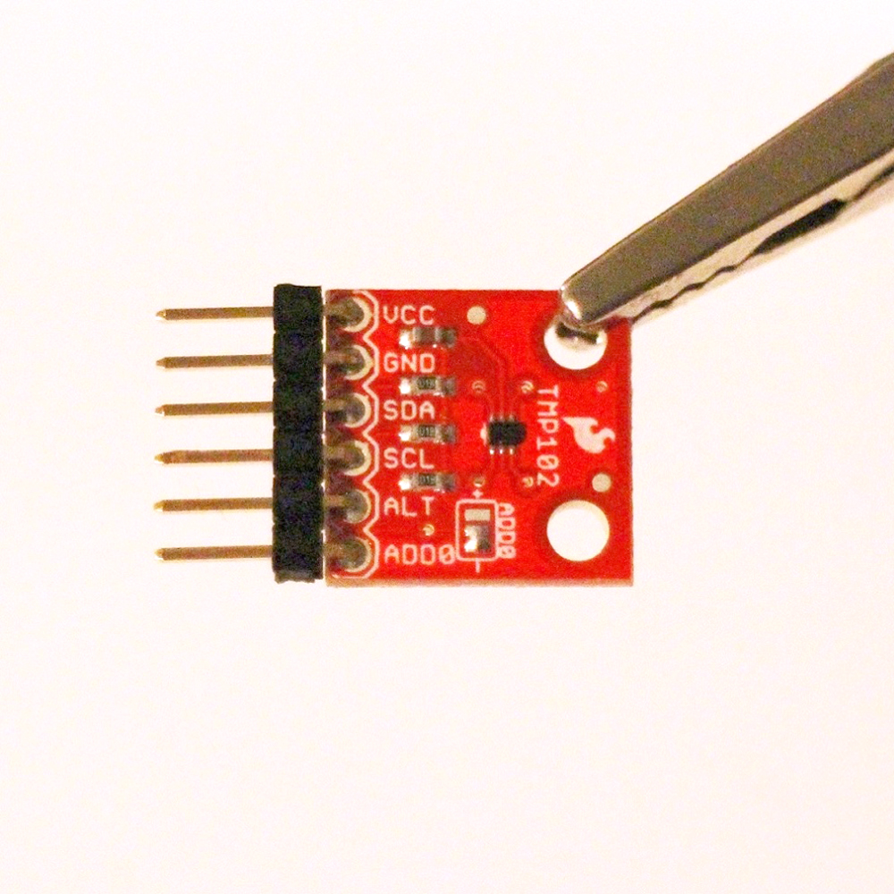
_Find your access token under the "Settings" tab._ Solder header pins to the SparkFun temperature sensor (TMP102).

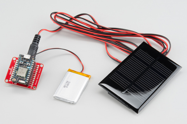
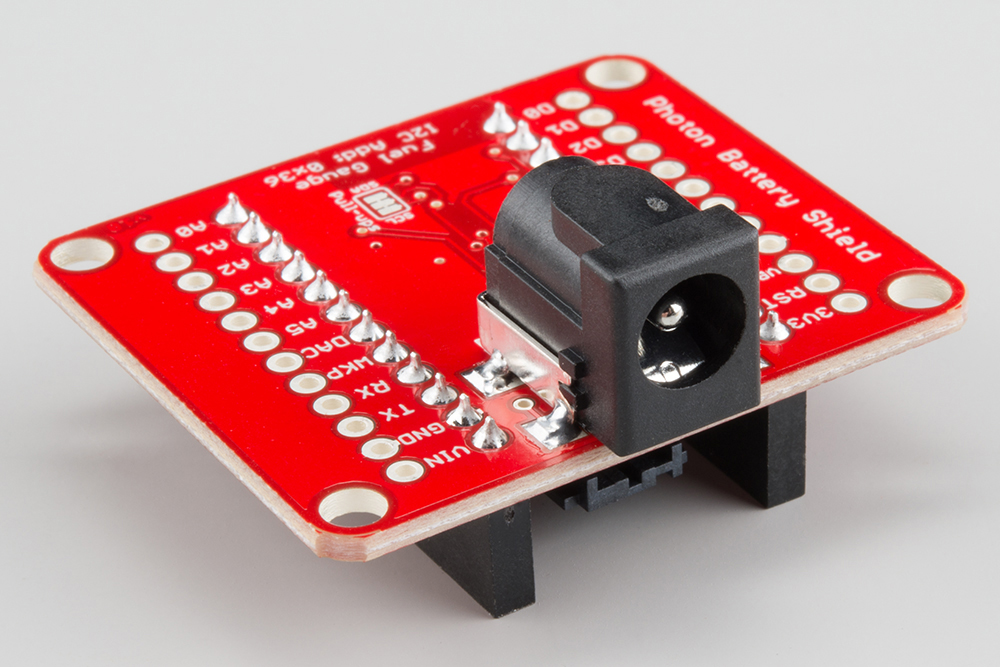
Solder the DC barrel jack onto the bottom of the Photon Battery Shield.

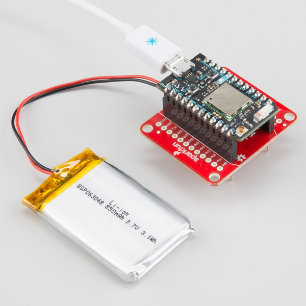
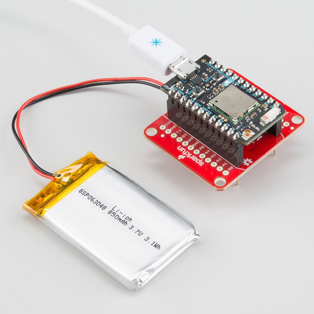
Plug the Photon into the Photon Battery Shield. Be sure that the rounded edges of the Photon line up with the rounded lines on the battery shield. Connect the battery and solar panel to the respective connectors. Check that the Photon powers on and connects to WiFi.
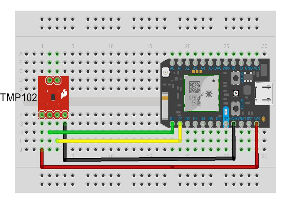
Connect the TMP102 temperature sensor to Photon battery shield pins with the breadboard jumper wires (or stranded 22 gauge insulated wire).

The green wire corresponds to the SDA pins, yellow wire to the SCL pins. This project only needs four (4) of the six (6) pins on the TMP102: VCC, GND, SDA and SCL. If you want to connect multiple temperature sensors using the I2C lines, you can use the ADDR0 pin to changes the device address for each sensor (See the I2C communication tutorial for help with this).
Connect TMP102 VCC pin to the Photon 3.3V source and GND to a Photon GND pin. Connect the TMP102 SDA pin to the Photon D0 pin and the SCL pin to the Photon D1 pin.
You can keep the final system on a breadboard or transfer it to a PCB board.
