Pi Servo pHAT (v2) Hookup Guide
 QCPete, santaimpersonator
 Introduction
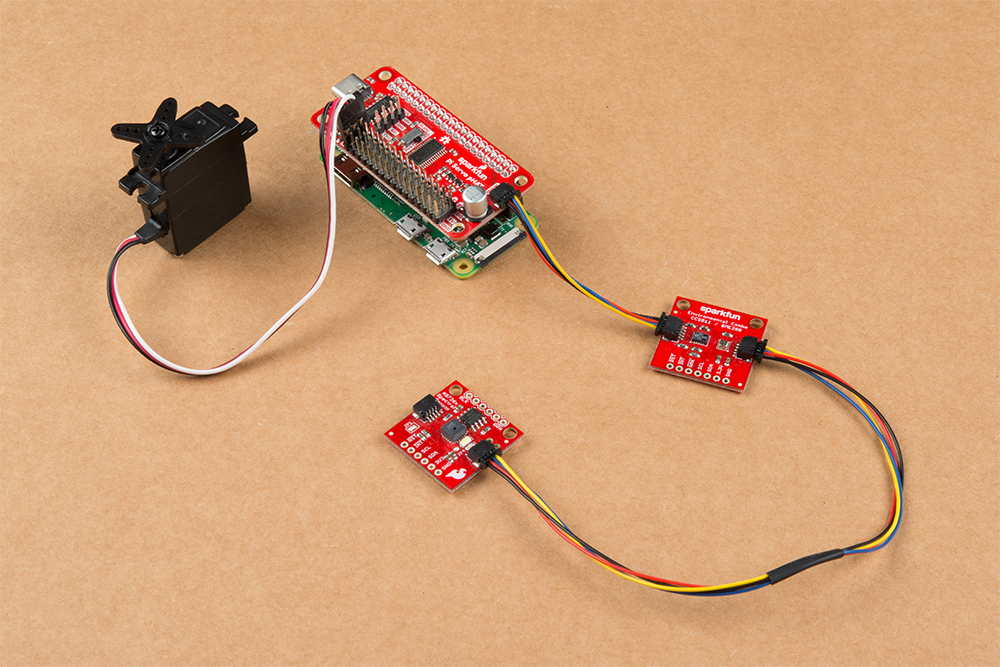
The SparkFun Pi Servo pHAT provides your Raspberry Pi with 16 PWM channels that can be controlled over I2C. These channels are broken out in a header combination that is perfect for connecting servo motors. Additionally, the PWM channels can control other PWM devices as well.
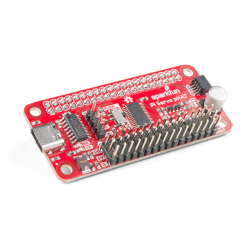
Furthermore, the Pi Servo pHAT can be used for a serial terminal connection to remotely control the Raspberry Pi, without the need for a monitor and keyboard (header used by the Sphero RVR). As an added bonus, we have provided a Qwiic connector for users to easily interface with the I2C bus using the Qwiic system. Who says you can't have it all?
Required Materials
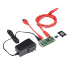
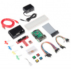
To get started with the Pi Servo pHAT, you will need a Raspberry Pi board with headers. There are several options that can be found under the Raspberry Pi Board product category. Additionally, we also offer these boards in various kits.

(Some, but not all of our Raspberry Pi kits include a Raspberry Pi. Be sure to double check the Includes tab of the associated product page. Additionally, the Sphero RVR kits will include this Pi Servo pHAT.).
There are a few additionally accessories that you will need to use your Raspberry Pi.
You will need an microSD Card, Power Supply, and USB-C Cable (optional) at minimum to run your Raspberry Pi. There are two options for the microSD card, a NOOBS card that comes pre-flashed with the OS need to run your Raspberry Pi or a blank SD card that can be flashed using the files and instructions from the Raspberry Pi Foundation page.


(To flash your own SD card, you will also want to grab a microSD USB adapter.)
Last of all, to test the functionality of the Pi Servo pHAT you will want a servo motor.

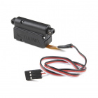
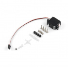
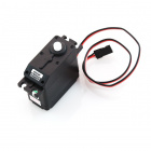
(Any "standard" 5V servo in our catalog should work. Keep in mind when purchasing, the continuous rotation servos behave differently from the normal servos.)
Required Tools
No tools are required to used this product. However, you may need a soldering iron, solder, and/or general soldering accessories to solder modify the jumpers or solder on headers to your Raspberry Pi board (if it didn't come with them).


Suggested Reading
Below are several tutorials and hookup guides covering various topics that we suggest users get familiar with before beginning this hookup guide. As a supplement, the hookup guides for the previous Pi Servo Hat are listed as well.
Raspberry Pi SPI and I2C Tutorial
Hobby Servo Tutorial
Setting Up the Pi Zero Wireless Pan-Tilt Camera
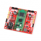
Pi Servo Hat Hookup Guide
Getting Started with the Raspberry Pi Zero Wireless
Python Programming Tutorial: Getting Started with the Raspberry Pi
The Pi Servo pHAT also provides a Qwiic connector to take advantage of our new Qwiic system. We recommend familiarizing yourself with the Logic Levels and I2C tutorials before using it. Click on the banner above to learn more about our Qwiic products.
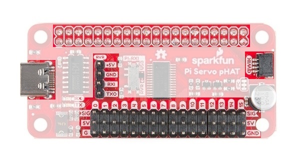
Hardware Overview
There are several functional components of the hat, which are designed to be as foolproof as possible. Although we have attempted to take precautions to guard against the most common user errors, users should still be wary. Most users may already be aware of these common pitfalls. However, if you have forgotten or maybe you have never used a Raspberry Pi (or similar single board computer), they are highlighted throughout this section just in case. There is a lot of detailed content in this section; in general, users primarily need to:
- Be cautious of any loose connections and avoid shorting or bridging 5V and 3.3V on the Raspberry Pi.
- Be aware of any potential current draw limitations.
Power
The power circuitry of the Pi Servo pHAT is more complex than most of the boards we produce. This is primarily due to the fact that is has to be able to handle 3 different power supplies (listed below) as well as 2 different voltage levels. The following subsections will cover the intricate details of the power circuitry on the Pi Servo pHAT.
3.3V Power
⚡ Danger: As a design requirement for Pi hats, power cannot be applied into the 3.3V pin from the hat.
Although unlikely, users should still double check that no power will be applied into the Qwiic connection since there is no circuit protection on the 3.3V line of the Servo Pi pHAT. Any application of power to the 3.3V pin through the Qwiic connector, the primary access point, from another device will likely damage your Raspberry Pi.
On the Pi Servo pHAT, 3.3V power is drawn from the Raspberry Pi 3.3V pin, on the 40-pin GPIO header, to power your Qwiic devices and for logic level translation. You cannot power the Raspberry Pi through the 3.3V pin; in fact, you should never connect another power source to this pin. It is intended to be used only as a power output for the Qwiic connect system.
The 3.3V line is primarily used to power any connected Qwiic devices. In general most users will not reach the current limitations of the Raspberry Pi. However, if you intend to sink a bunch of current or have a ton of Qwiic devices, make sure double check your current draw and the limitations of the Raspberry Pi you are using. As an example, the Raspberry Pi Zero W uses a PAM2306 switching 3.3V regulator (found in the schematic for power regulation), which is rated up to a 1A output current.
Is a 1 amp current draw gonna get HOT? Let's see...
-
Regulating from 5V down to 3.3V is a ΔV of 1.7V.
5V - 3.3V = 1.7V -
At 1A, this is 1.7W.
1.7V x 1A = 1.7W -
With a Thermal Resistance (Junction to Ambient) of 60 °C/Watt, this should cause an increase of 102 °C.
1.7W x 60 °C/W = 102 °C -
Add room temp (27 °C), this takes us up to 129 °C.
102 °C + 27 °C = 129 °C
This is well below the Maximum Junction Temperature of 150 °C. Should be good to go for 1A!
Logic Level Conversion
The 3.3V pin also provides a reference voltage for the MOSFET logic level converters to the PCA9685 PWM controller. It is all connected to the I2C pullup resistors for the Qwiic connector.
5.0V Power
The three different power sources to the 5V line of the servo header are: the 5V pin from the 40-pin header of the Raspberry Pi (power supply connected to the Raspberry Pi), the 5V pin from the RVR serial connection header, and the USB-C female connector. The power protection and control circuitry on the Pi Servo pHAT allows these to be used either individually or in tandem combinations.
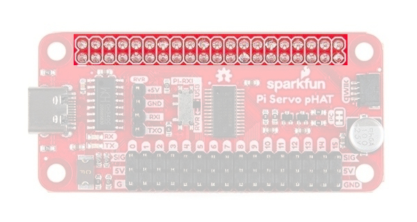
40-Pin Female Header: Power to and/or from the Raspberry Pi is accessed through the 40-pin header. This female header provides several connections to a Raspberry Pi. For power, the 5V pin and 3.3V pins are used.
 The 40-pin GPIO header connection to the Raspberry Pi. Click to enlarge.
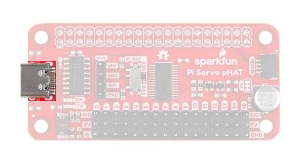
USB-C Connector: This connector can be used to power the servo motors as well as the Raspberry Pi. It can also be used to connect to the Pi via serial port connection (see Serial-UART section below).
 The USB-C connection to the Pi Servo pHAT. Click to enlarge.
RVR Header: This 4-pin header can be used to power the servo motors as well as the Raspberry Pi. It can also be used to connect to the Pi via serial port connection (see Serial-UART section below).
 The Sphero RVR 4-pin header connection to the Pi Servo pHAT. Click to enlarge.
Power Control & Protection
Although we have attempted to take precautions to guard against reverse current, users should still be wary of what they are doing.
⚡ A short between the 5V and 3.3V lines will permanently put your Raspberry Pi out of commission.
⚡ Power cannot be applied into the 3.3V pin (or Qwiic Connector) from the Servo Pi pHAT. Any application of power to the 3.3V pin of the Raspberry Pi will likely damage it; there is no circuit protection.
- Always calculate your expected and maximum current draw to prevent issues.
⚡ A proper USB port or power supply should be used when providing power through the USB-C connection. A USB 2.0 port supplies a regulated 5V, but is limited to about 500mA. Drawing more current than the USB port on your computer can supply, will most likely cause your computer to freak out and may even damage the power controller.
🔥 Over drawing current from the 3.3V line may strain the 3.3V regulator. The regulator on a Raspberry Pi Zero W will get pretty toasty at 1A.
⚡ The fuse on the USB-C connection is part of the power protection circuitry. Only use use the fuse bypass jumper if you know what you are doing; otherwise, a small mistake could cost you your whole project.
Reverse Current Protection
The Pi Servo pHAT controls 5V power from three different sources, the 5V pin from the 40-pin header of the Raspberry Pi, the 5V pin from the RVR serial connection header, and the USB-C female connector. To provide reverse current protection, the board utilizes circuitry that acts as an ideal diode, a design used on the Raspberry Pi 3 and a requirement for Raspberry Pi hats.
The ideal diode circuit protection prevents back power from the Pi Servo pHAT to either of the USB-C and RVR connections. When using multiple power sources on the Pi Servo pHAT, there is possibility that the power sources will provide conflicting input voltages. If the voltage differential is great enough between the power supplies, a reversal of the flow of power can occur and current pushed back into a power source. This can potentially damage devices, including your computer. For more information, check out the Raspberry Pi Backpowering Guidelines.
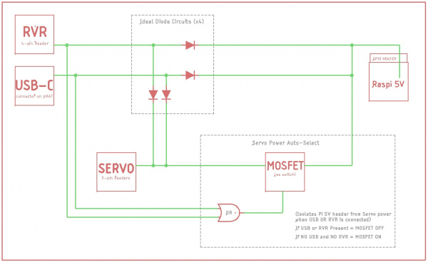
As shown in the functional block diagram above, the USB-C and RVR inputs are both protected against possible back power from either the Raspberry Pi and/or servo power sources with ideal diodes. However, in order to allow power to pass from the Pi Servo pHAT to the Raspberry Pi for a headless setup, power protection or isolation circuitry was't implemented on the 5V GPIO pin. This means that current can freely flow back into the Raspberry Pi to provide power, but may be a concern for the Raspberry Pi Zero, Zero W, 3B+, and 3A+ models, which don't include reverse current protection for their power supplies.
This would be a concern if the 5V power supply on the Raspberry Pi (micro-B USB connector) was somehow sinking current from external power provided through either the USB-C or RVR connections on the Pi Servo pHAT. However, in reality, there still is a small voltage drop across the ideal diodes, the 5V rail on the Raspberry Pi does have some tolerance, and it is not very likely that the power supply on the Raspberry Pi would be sinking current either. In the off chance that you decide to be a mad scientist and test the limits of the boards, there is a power isolation jumper can be manually cut since there is no circuit protection from the 5V line on the Pi Servo pHAT to the 5V line of the Raspberry Pi.
Power Control
Also shown in the functional block diagram above, is a MOSFET acting as an automated switch to manage possible power from the Raspberry Pi. If either the RVR header or the USB-C connector provide 5V, then the power from Raspberry Pi's GPIO header is disconnected from the servo 5V rail. The table below outlines the possible power source combinations.
| Power Sources | Description | ||
|---|---|---|---|
| Pi GPIO | USB-C | RVR Header | |
| X | X | O |
Raspberry Pi powered primarily by own power supply. Servos pull power from USB-C (MOSFET closed; no power from Pi). |
| X | O | X |
Raspberry Pi powered primarily by own power supply. Servos pull power from RVR header (MOSFET closed; no power from Pi). |
| X | X | X |
Raspberry Pi powered primarily by own power supply. Servos pull power from USB-C or RVR header, whichever works best (MOSFET closed; no power from Pi). |
| O | X | X | Raspberry Pi and servos are from USB-C or RVR header, whichever is best. |
| O | O | X | Powered by individual power supplies. |
| O | X | O | |
| X | O | O | |
No outlined in the table is the possibility of power being connected to the servo 5V rail.
USB-C Fuse
On the Pi Servo pHAT there is a fuse (2.5A hold and 5A trip) that limits current draw over the USB-C connection. If more than 5A is drawn, it automatically throttles the current draw and/or disconnects power until the load is removed. A bypass jumper is provided for users who want to remove this limitation; however, users should know what they are doing when using this jumper. As a recommendation, if you do not know what you are doing, you should leave this jumper alone. (see Jumpers section below)
Power Isolation
There is a power isolation jumper connected to the 40-pin GPIO header on the Pi Servo pHAT. This jumper can be cut to isolate the 5V pin of the Raspberry Pi from the 5V used on the Pi Servo pHAT. This is usually used when you expect to be using heavy loads or are worried about noise transferring back to the Raspberry Pi, which often results in intermittent power loss. (see Jumpers section below)
Cutting this jumper does not affect the serial UART connection. However, the jumper does need to be bridged, if you want to power the Raspberry Pi from the Pi Servo pHAT again.
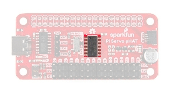
PCA9685
The PCA9685 provides I2C control over the 16-channels of 12-bit pulse width modulation (PWM) on the Pi Servo pHAT. The PCA9685 is designed primarily for LED control, but can be used for other PWM devices like servos.
| Characteristic | Description |
|---|---|
| Operating Voltage (VDD) | 2.3 V to 5.5 V (Hardwired: 5V) |
| Operating Temperature | -40°C to 85°C |
| PWM Outputs |
16 Totem pole outputs (Default: Open-Drain) Sink 25 mA or Source 10 mA (at 5V) Shared PWM frequency Supports hot insertion |
| PWM Frequency | 24Hz to 1526 Hz (Default (1Eh): 200Hz) |
| PWM Resolution | 12-bit (4096 steps of control) |
| Duty Cycle | 0% to 100% (adjustable) |
| Oscillator |
Internal: 25 MHz (Hardwired) External: 50 MHz (max.) input (unavailable) |
| I2C Address |
62 hardware configurable addresses (Hardwired: 0x40) 4 programmable addresses to allow simultaneous groups control of multiple devices:
|
Although, the PWM frequency of all the channels are shared, the duty cycle of the 16 channels of PWM output can be controlled individually. This allows the PCA9685 to control servos or LEDs on each of the outputs. For LEDs, this allows the channels to control or drive the brightness; or the position on servos.
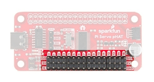
Servo/PWM Headers
The Pi Sevro pHAT can be utilized with various PWM devices, the most typically application will be servos and LEDs. These headers are spaced out to make it easier to attach servo motors to them. Additionally, they are broken out in the standard 3-pin configuration for most hobby-type servo motor connectors.
Serial UART Connections
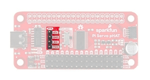
A Raspberry Pi can be interfaced over a serial connection through the Pi Servo pHAT. There are two different access points to the serial UART; the 4-pin header for the Sphero RVR and the USB-C connection. Control over which interface is used is provided by the RX switch on the Pi Servo pHAT.
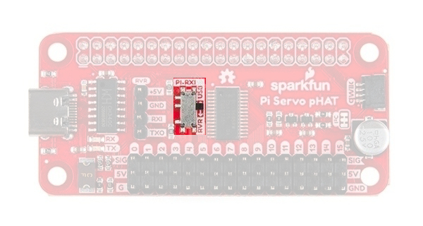
The indication of which connection is used should be straight forward. The interface that is labeled (USB or RVR) on the side that the switch is on (black nub), will indicate the TX connection to the RX pin of the Raspberry Pi for serial communication. As shown in the picture above, the TX line from the USB-C interface is connected to the RX pin of the Raspberry Pi. To change to TX line of the Sphero RVR 4-pin header, users just need to follow the arrow and slide the switch into the RVR position.
For more tips and details on serial communication, read our Serial Communication and Terminal Basics tutorials.
USB-C Connector
This connector can be used for power and to connect to the Pi via serial port connection, to access the Raspberry Pi remotely, without needing to use a monitor and keyboard to set up the Pi (see Headless Raspberry Pi Setup tutorial).
On the Pi Servo pHAT there is a fuse that limit current draw over the USB-C connection. If more than 5A is drawn, it automatically throttles the current draw and/or disconnects power until the load is removed.
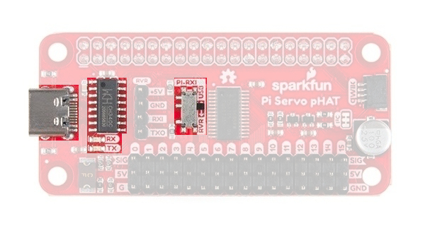
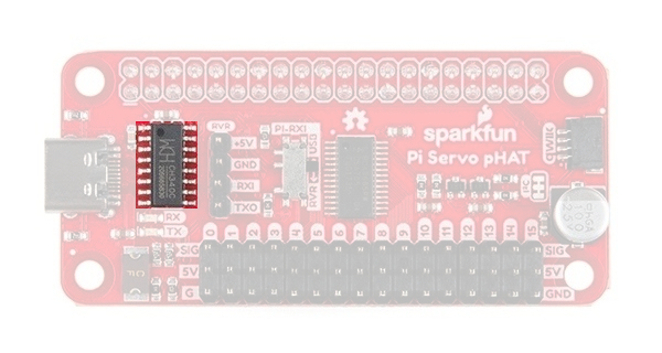
CH340C
The CH340C is a USB-to-Serial adapter from WCH. It is used to convert data to and from USB-C connection to a serial terminal. The driver for the CH340C chip will need to be installed on your computer. We have tested and confirmed that the driver works on Windows 7, Windows 10, Mac OSX High Sierra, and Raspbian Stretch (11-13-2018 release) for the Raspberry Pi. On all operating systems, if you have previously installed the CH340G drivers, you will need to uninstall those drivers first before updating to the new CH340C driver. For more information, check out our How to Install CH340 Drivers Tutorial.
How to Install CH340 Drivers
August 6, 2019
Whenever you send or receive serial data on the USB-C connection, you should seen the RX (yellow) and/or TX (green) LEDs flashing. The RX pin is shares a connection with the 4-pin RVR header and may flash when it is receiving data.
RVR Header
The Sphero RVR requires a 4-pin header to access a Raspberry Pi. On the Pi Servo pHAT we have broken out this connection for a painless integration with the Sphero RVR.

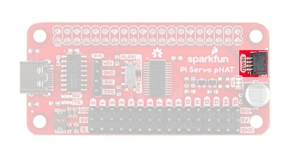
Qwiic Connector
A Qwiic connector is provided for additional compatibility with our Qwiic line of products. The Qwiic system is intended to be a quick, hassle-free cabling/connector system to conveniently add your favorite I2C devices. The Qwiic connector is tied to the I2C pins of the Raspberry Pi and draws power directly from the 3.3V pins.
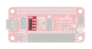
Jumpers
There are a few jumpers broken out on this board to easily modify a few hardware connections without having to rework individual components. If you are ot sure how to cut a jumper, please read our tutorial here! As a recommendation, please review what each jumper does before making a modification. This is especially true for the fuse bypass jumper, which can have dire consequences.
Power Isolation
This jumper is closed by default. It can be cleared/opened to isolate the power sources on the Pi Servo pHAT from the Pi 5V power rail.
Fuse Bypass
The bypass jumper is provided for users who want to remove the current limitation of the fuse on the USB-C connection; however, users should know what they are doing when using this jumper. The fuse is rated to a 2.5A hold and 5A trip current.
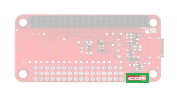
As a recommendation, if you don't know what you are doing, you should leave this jumper alone. The USB-C is capable of delivering tremendous amounts of power and can easily damage hardware.
I2C Pull-Up
Cutting the I2C jumper will disconnect the 10 kΩ pull-up resistors from the I2C bus.
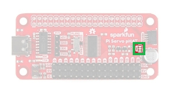
As an example, if you have multiple Qwiic devices with pull-up resistors connected, you may want to cut these jumpers. When there are multiple devices on the I2C bus with pull-up resistors, the equivalent parallel resistance may create too strong of a pull-up for the bus to operate correctly.
Hardware Assembly
Note: This tutorial assumes that users are familiar with the Raspberry Pi and have a general knowledge base of Python. If you have unfamiliar with these items, as a starting point, we suggest setting up your Raspberry Pi, familiarizing yourself with the graphics user interface (GUI), and then learning the basics of Python. Below are resources to get you started:
- Resources for getting started with the Raspberry Pi can be found on the Raspberry Pi Foundation's website. They also provide documentation for the Raspberry Pi, forum support for the Raspberry Pi, and there is a broad community so finding resources online is just a simple search online.
- Resources for getting started with the Python can be found on the Python website. They also provide extensive documentation and there is a relatively large community so accessing alternative resources online is simple.
Raspberry Pi
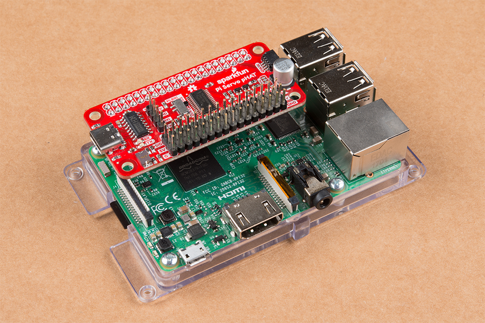
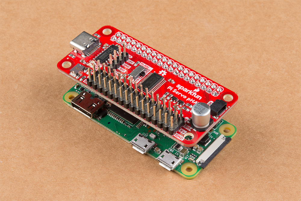
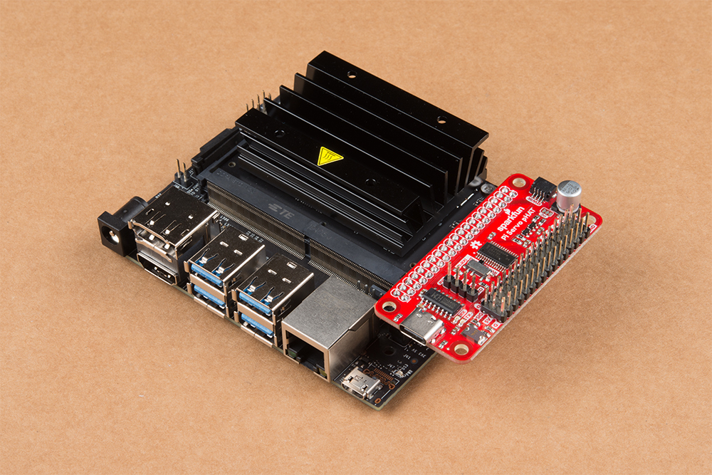
Assembling the Pi Servo pHAT (v2) with a Raspberry Pi is pretty straight forward. First make sure that nothing is powered. Then, just stack the board onto the Raspberry Pi so that the PCBs line up on top of each other; the Pi Servo pHAT is NOT meant to protrude out to the side.
- Stacking the Pi Servo pHAT with the PCB protruding to the side of the Raspberry Pi instead of on top (or above) will incorrectly connect pins and will most likely damage something.
- Although usually minimal, even when connecting a Raspberry hat there is a chance to short, brown-out, and/or damage something. As a best practice, you should never plug in a hat while anything is powered (including the hat, servos, LEDs, or additional qwiic boards).
- Make sure you aren't using a Raspberry Pi 4 or the Debian Buster image. Both have yet to be tested for use with this product.
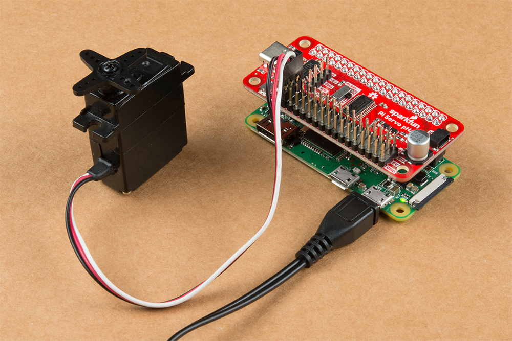
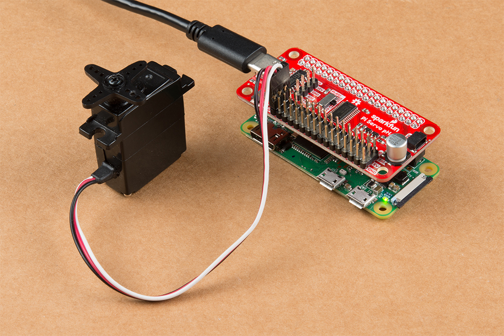
- Never plug in a servo while your Raspberry Pi is running. The sudden current spike needed to power your servo will reset your Raspberry Pi. Always plug in all of your servos first, and then boot up.
Never plug in a servo while your Raspberry Pi is running. The sudden current spike needed to power your servo will reset your Raspberry Pi. Always plug in all of your servos first, and then boot up.
Sphero RVR
Unfortunately, this tutorial won't cover the use of the Pi Servo pHAT with the Sphero RVR. However, links to the assembly guides and getting started tutorial are provided below.
Basic Autonomous Kit for Sphero RVR Assembly Guide
Advanced Autonomous Kit for Sphero RVR Assembly Guide
Getting Started with the Autonomous Kit for the Sphero RVR
Other Single Board Computers
Using this hat with other single board computers (SBCs) like the Nvidia Jetson or Google Coral is a similar process. Just make sure that you have the HAT aligned in the proper orientation. For example, with the Nvidia Jetson, the hat should be protruding outwards from the board (do not try to remove the heatsink to make the HAT fit, that is the wrong orientation).
Power
As described in the Hardware Overview, 5V power to the servo headers is provided through three different sources.
Servos
In this tutorial we will be testing out a hobby servo on channel "0". Based on the servo that you are using, try looking at the hobby servo's datasheet or referring to some of the standard servo connector pinouts listed in this tutorial.
Qwiic Devices
The Qwiic connection system makes it easy to add your favorite Qwiic compatible sensor or device.
Python Package Overview
Note: This package assumes you are using the latest version of Python 3. If this is your first time using Python or I2C hardware on a Raspberry Pi, please checkout our tutorial on Python Programming with the Raspberry Pi and the Raspberry Pi SPI and I2C Tutorial.
*On the Raspberry Pi, Python 2 and 3 are included with the Raspbian OS (with desktop and recommended software) image.
Support Tip: Don't forget to double check that the hardware I2C connection is enabled on your Raspberry Pi or other single board computer.
There are two Python packages for this product. Qwiic_PCA9685_Py is an underlying package for the operation of the PCA9685 PWM controller IC. While, PiServoHat_Py is a package, built specifically for this product, to control servos. We've written these packages to easily start controlling servos with the Pi Servo pHAT.
Installation
To install the Python packages for this product, it is recommended that users install the SparkFun Qwiic Python package, which installs all the available Python packages for our Qwiic products and includes the required I2C driver package. On systems that support PyPi installation via pip3 (use pip for Python 2) is simple, using the following commands:
For all users (note: the user must have sudo privileges):
language:bash
sudo pip3 install sparkfun-qwiic
For the current user:
language:bash
pip3 install sparkfun-qwiic
Qwiic_PCA9685_Py
You can install the sparkfun-sparkfun-qwiic-pca9685 Python package hosted by PyPi. If you prefer to manually download and install the package from the GitHub repository, you can grab them here (*Please be aware of any package dependencies. You can also check out the repository documentation page, hosted on ReadtheDocs.):
PyPi Installation
This repository is hosted on PyPi as the sparkfun-qwiic-pca9685 package. On systems that support PyPi installation via pip3 (use pip for Python 2) is simple, using the following commands:
For all users (note: the user must have sudo privileges):
language:bash
sudo pip3 install sparkfun-qwiic-pca9685
For the current user:
language:bash
pip3 install sparkfun-qwiic-pca9685
Local Installation
To install, make sure the setuptools package is installed on the system.
Direct installation at the command line (use python for Python 2):
language:bash
python3 setup.py install
To build a package for use with pip3:
language:bash
python3 setup.py sdist
A package file is built and placed in a subdirectory called dist. This package file can be installed using pip3.
language:bash
cd dist
pip3 install sparkfun_qwiic_pca9685-<version>.tar.gz
Python Package Operation
As this is an underlying package for the PCA9685 PWM controller IC, we will not go into the details of the package operation. However, users are welcome to check out the ReadtheDocs documentation.
PiServoHat_Py
You can install the sparkfun-pi-servo-hat Python package hosted by PyPi. If you prefer to manually download and install the package from the GitHub repository, you can grab them here (*Please be aware of any package dependencies. You can also check out the repository documentation page, hosted on ReadtheDocs.):
PyPi Installation
This repository is hosted on PyPi as the sparkfun-pi-servo-hat package. On systems that support PyPi installation via pip3 (use pip for Python 2) is simple, using the following commands:
For all users (note: the user must have sudo privileges):
language:bash
sudo pip3 install sparkfun-pi-servo-hat
For the current user:
language:bash
pip3 install sparkfun-pi-servo-hat
Local Installation
To install, make sure the setuptools package is installed on the system.
Direct installation at the command line:
language:bash
python setup.py install
To build a package for use with pip3:
language:bash
python setup.py sdist
A package file is built and placed in a subdirectory called dist. This package file can be installed using pip3.
language:bash
cd dist
pip3 install sparkfun_pi_servo_hat-<version>.tar.gz
Python Package Operation
Below is a description of the basic functionality of the Python package. This includes the package organization, built-in methods, and their inputs and/or outputs. For more details on how the Python package works, check out the source code and the sensor datasheet.
Dependencies
This Python package has a very few dependencies in the code, listed below:
language:python
import time             # Time access and conversion package
import math             # Basic math package
import qwiic_pca9685    # PCA9685 LED driver package
Default Variables
The default variables, in the code, for this Python package are listed below:
language:python
# Device Name:
_DEFAULT_NAME = "Pi Servo HAT"

# Fixed Address:
_AVAILABLE_I2C_ADDRESS = [0x40]

# Default Servo Frequency:
_DEFAULT_SERVO_FREQUENCY = 50   # Hz

# Special Use Addresses:
gcAddr = 0x00       # General Call address for software reset
acAddr = 0x70       # All Call address- used for modifications to
                    # multiple PCA9685 chips reguardless of thier
                    # I2C address set by hardware pins (A0 to A5).
subAddr_1 = 0x71    # 1110 001X or 0xE2 (7-bit)
subAddr_2 = 0x72    # 1110 010X or 0xE4 (7-bit)
subAddr_3 = 0x74    # 1110 100X or 0xE8 (7-bit)
Class
PiServoHat() or PiServoHat(address, debug=None)
This Python package operates as a class object, allowing new instances of that type to be made. An __init__() constructor is used that creates a connection to an I2C device over the I2C bus using the default or specified I2C address.
The Constructor
A constructor is a special kind of method used to initialize (assign values to) the data members needed by the object when it is created.
__init__(address, debug)
_AVAILABLE_I2C_ADDRESS variable. The All Call address is 0x70.
0: Don't print debug statements.
1: Print debug statements.
True: Connected to I2C device on the default (or specified) address.
False: No device found or connected.
Functions
A function that is an attribute of the class, which defines a method for instances of that class. In simple terms, they are objects for the operations (or methods) of the class.
.restart()
Soft resets the PCA9685 chip and then clears the MODE1 register to restart the PWM functionality. The PWM frequency is also returned to the default 50 Hz setting.
.get_pwm_frequency()
Reads the PWM frequency used on the outputs.
Range: 24 Hz to 1526 Hz
.set_pwm_frequency(frequency)
Configures the PWM frequency used on outputs. 50 Hz is the default and recommended for most servos.
Range: 24 Hz to 1526 Hz
.get_servo_position(channel) or .get_servo_position(channel, swing)
Estimates the orientation of the servo arm in degrees. The estimation is based upon the timing that is configured for the PWM signal, on the specified channel.
Channel of Interest
Range: 0 to 15
90: Servo with 90° arm swing.
180: Servo with 180° arm swing.
Estimated servo arm position.
.move_servo_position(channel, position) or .move_servo_position(channel, position, swing)
Moves servo to specified location in degrees.
Channel of Interest
Range: 0 to 15
Specified servo arm position.
Input: Value
90: Servo with 90° arm swing.
180: Servo with 180° arm swing.
.set_duty_cycle(channel, duty_cycle)
Moves servo to specified location based on duty-cycle.
Channel of Interest
Range: 0 to 15
Duty-Cycle (Percentage)
Range: 0 to 100 (%) (Resolution: 1/4096)
Upgrading Packages
In the future, changes to the Python packages might be made. Updating the installed packages has to be done individually for each package (i.e. sub-modules and dependencies won't update automatically and must be updated manually). For the SomePackage Python package, use the following command (use pip for Python 2):
For all users (note: the user must have sudo privileges):
language:bash
sudo pip3 install --upgrade SomePackage
For the current user:
language:bash
pip3 install --upgrade SomePackage
Python Examples
The example code for this product is located in the GitHub repository for the Python package; it is also hosted with the ReadtheDocs documentation:
- Example 1: Full Sweep for 90 Degree Servo
- Example 2: Full Sweep for 180 Degree Servo
- Example 3: Get Servo Position for 180 Degree Servo
- Example 4: Change PWM Frequency for 180 Degree Servo
To run the examples, simple download or copy the code into a file. Then, open/save the example file (if needed) and execute the code in your favorite Python IDE. For example, with the default Python IDLE click Run > Run Module or use the F5 key. To terminate the example use the Ctrl + C key combination.
Example 1
We will only cover the first example; however, we will also be breaking down how the code works and explaining how it functions.
Import Dependencies
The first part of the code, imports the required dependencies to operate.
language:python
import pi_servo_hat
import time
Initialize Constructor
This line instantiates an object for the device.
language:python
test = pi_servo_hat.PiServoHat()
Soft Restart
This line soft resets the PCA9685 chip, clears the MODE1 register, and returns the PWM frequency to the default 50 Hz.
language:python
test.restart()
Test Run
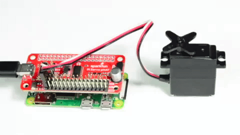
This section of the code moves the servo arm to 0° by outputting a 1 ms PWM signal, pausing for a second, then it moves the arm to 90° by outputting a 2 ms PWM signal, and holds the position for a second.
language:python
# Moves servo position to 0 degrees (1ms), Channel 0
test.move_servo_position(0, 0)

# Pause 1 sec
time.sleep(1)

# Moves servo position to 90 degrees (2ms), Channel 0
test.move_servo_position(0, 90)

# Pause 1 sec
time.sleep(1)
Note: The inputs for the servo position will be approximate, as it is limited to the resolution of the PWM signal. Users can move to Example 3 for a demonstration of this.
Sweep
The final section of the code repeatedly sweeps the servo arm from 0° to 90° and then back. The code iterates with ~1° increments and prints the input position.
language:python
while True:
    for i in range(0, 90):
        print(i)
        test.move_servo_position(0, i)
        time.sleep(.001)
    for i in range(90, 0, -1):
        print(i)
        test.move_servo_position(0, i)
        time.sleep(.001)
Note: As nothing is perfect, the servo position may vary from the expected input. This limitation is usually due to the accuracy of the servo; however, part of this can be attributed to the timing on the PWM signal. (The PWM signal to the servo is affected by the resolution of the output and the PWM frequency; however, these factors are negligible in comparison to the servo accuracy.)
With servos, you get what you pay for. High quality performance servos cost significantly more than the cheaper alternatives. Various factors of their performance, including size, torque, response time, and position accuracy attribute to cost. Therefore, if you are using a cheaper alternative you may need to compensate in the software.
Additionally, with some servos, the full range of the servo arm rotation extends beyond the expected 90° or 180°. The final commented section of the code can be used to take advantage of this factor; however, it should be used with caution as it may permanently damage or destroy the servo.
Python Examples (archived)
We'll go over in some detail here how to access and use the Pi Servo pHAT in Python. Full example code is available in the product GitHub repository.
Set Up Access to SMBus Resources
First point: in most OS level interactions, the I2C bus is referred to as SMBus. Thus we get our first lines of code. This imports the smbus module, creates an object of type SMBus, and attaches it to bus "1" of the Pi's various SMBuses.
language:python
import smbus
bus = smbus.SMBus(1)
We have to tell the program the part's address. By default, it is 0x40, so set a variable to that for later use.
language:python
addr = 0x40
Next, we want to enable the PWM chip and tell it to automatically increment addresses after a write (that lets us do single-operation multi-byte writes).
language:python
bus.write_byte_data(addr, 0, 0x20)
bus.write_byte_data(addr, 0xfe, 0x1e)
Write Values to the PWM Registers
That's all the setup that needs to be done. From here on out, we can write data to the PWM chip and expect to have it respond. Here's an example.
language:python
bus.write_word_data(addr, 0x06, 0)
bus.write_word_data(addr, 0x08, 1250)
The first write is to the "start time" register for channel 0. By default, the PWM frequency of the chip is 200Hz, or one pulse every 5ms. The start time register determines when the pulse goes high in the 5ms cycle. All channels are synchronized to that cycle. Generally, this should be written to 0.
The second write is to the "stop time" register, and it controls when the pulse should go low. The range for this value is from 0 to 4095, and each count represents one slice of that 5ms period (5ms/4095), or about 1.2us. Thus, the value of 1250 written above represents about 1.5ms of high time per 5ms period.
Servo motors get their control signal from that pulse width. Generally speaking, a pulse width of 1.5ms yields a "neutral" position, halfway between the extremes of the motor's range. 1.0ms yields approximately 90 degrees off center, and 2.0ms yields -90 degrees off center. In practice, those values may be slightly more or less than 90 degrees, and the motor may be capable of slightly more or less than 90 degrees of motion in either direction.
To address other channels, simply increase the address of the two registers above by 4. Thus, start time for channel 1 is 0x0A, for channel 2 is 0x0E, channel 3 is 0x12, etc. and stop time address for channel 1 is 0x0C, for channel 2 is 0x10, channel 3 is 0x14, etc. See the table below.
| Channel # | Start Address | Stop Address |
|---|---|---|
| Ch 0 | 0x06 | 0x08 |
| Ch 1 | 0x0A | 0x0C |
| Ch 2 | 0x0E | 0x10 |
| Ch 3 | 0x12 | 0x14 |
| Ch 4 | 0x16 | 0x18 |
| Ch 5 | 0x1A | 0x1C |
| Ch 6 | 0x1E | 0x20 |
| Ch 7 | 0x22 | 0x24 |
| Ch 8 | 0x26 | 0x28 |
| Ch 9 | 0x2A | 0x2C |
| Ch 10 | 0x2E | 0x30 |
| Ch 11 | 0x32 | 0x34 |
| Ch 12 | 0x36 | 0x38 |
| Ch 13 | 0x3A | 0x3C |
| Ch 14 | 0x3E | 0x40 |
| Ch 15 | 0x42 | 0x44 |
If you write a 0 to the start address, every degree of offset from 90 degrees requires 4.6 counts written to the stop address. In other words, multiply the number of degrees offset from neutral you wish to achieve by 4.6, then either add or subtract that result from 1250, depending on the direction of motion you wish. For example, a 45 degree offset from center would be 207 (45x4.6) counts either more or less than 1250, depending upon the direction you desire the motion to be in.
Examples
Below, are some convenient examples for users to draw from.
Example 1: 50 Hz Frequency
Unlike the higher-end or modern servos that can handle higher frequencies, most servos (often older and cheaper) prefer a 50 Hz PWM frequency and will struggle with a 200 Hz PWM frequency. Usually, they end up buzzing or over heating, while trying to search for hone/track their position.
Below is an example of how to configure the PCA9685 to drive at a 50 Hz PWM frequency. This does reduce the resolution of the servo arm position, but for most servos that was probably causing the servo to overheat anyways.
language:python
import smbus, time
bus = smbus.SMBus(1)
addr = 0x40

## Running this program will move the servo to 0, 45, and 90 degrees with 5 second pauses in between with a 50 Hz PWM signal.

bus.write_byte_data(addr, 0, 0x20) # enable the chip
time.sleep(.25)
bus.write_byte_data(addr, 0, 0x10) # enable Prescale change as noted in the datasheet
time.sleep(.25) # delay for reset
bus.write_byte_data(addr, 0xfe, 0x79) #changes the Prescale register value for 50 Hz, using the equation in the datasheet.
bus.write_byte_data(addr, 0, 0x20) # enables the chip

time.sleep(.25)
bus.write_word_data(addr, 0x06, 0) # chl 0 start time = 0us

time.sleep(.25)
bus.write_word_data(addr, 0x08, 209) # chl 0 end time = 1.0ms (0 degrees)
time.sleep(.15)
bus.write_word_data(addr, 0x08, 312) # chl 0 end time = 1.5ms (45 degrees)
time.sleep(.15)
bus.write_word_data(addr, 0x08, 416) # chl 0 end time = 2.0ms (90 degrees)

while True:
     time.sleep(.5)
     bus.write_word_data(addr, 0x08, 209) # chl 0 end time = 1.0ms (0 degrees)
     time.sleep(.5)
     bus.write_word_data(addr, 0x08, 312) # chl 0 end time = 1.5ms (45 degrees)
     time.sleep(.5)
     bus.write_word_data(addr, 0x08, 209) # chl 0 end time = 1.0ms (0 degrees)
     time.sleep(.5)
     bus.write_word_data(addr, 0x08, 416) # chl 0 end time = 2.0ms (90 degrees)
Example 2: Create a Function
This example creates simple functions to set the start and end times of the PWM signal based on the designated servo position for a specific channel. This example should make it easier for users to create their own scripts with more limited knowledge of the python language.
language:python
import smbus, time
bus = smbus.SMBus(1)
addr = 0x40

def servo_Init(channel):
     # Mapping Channel Register
     channel_0_start = 0x06
     channel_reg = 4*channel + channel_0_start

     # Write to Channel Register
     bus.write_word_data(addr, channel_reg, 0)


def servo_Pos(channel, deg_range, deg_position):
     # Mapping Channel Register
     channel_0_end = 0x08
     channel_reg = 4*channel + channel_0_end

     # Mapping Sevo Arm Position
     #   209 = 0 deg
     #   312 = 45 deg
     #   416 = 90 deg
     deg_0 = 209
     deg_max = 416
     pos_end_byte = lambda x: (deg_max-deg_0)/deg_range*x + deg_0

     # Write to Channel Register
     bus.write_word_data(addr, channel_reg, round(pos_end_byte(deg_position)))

## Running this program will move the servo to 0, 45, and 90 degrees with 5 second pauses in between with a 50 Hz PWM signal.

# Configure 50Hz PWM Output
bus.write_byte_data(addr, 0, 0x20) # enable the chip
time.sleep(.25)
bus.write_byte_data(addr, 0, 0x10) # enable Prescale change as noted in the datasheet
time.sleep(.25) # delay for reset
bus.write_byte_data(addr, 0xfe, 0x79) #changes the Prescale register value for 50 Hz, using the equation in the datasheet.
bus.write_byte_data(addr, 0, 0x20) # enables the chip

# Initialize Channel (sets start time for channel)
servo_Init(3)

# Run Loop
while True:
     time.sleep(.5)
     servo_Pos(3, 90, 0) # chl 3 end time = 1.0ms (0 degrees)
     time.sleep(.5)
     servo_Pos(3, 90, 45) # chl 3 end time = 1.5ms (45 degrees)
     time.sleep(.5)
     servo_Pos(3, 90, 0) # chl 3 end time = 1.0ms (0 degrees)
     time.sleep(.5)
     servo_Pos(3, 90, 90) # chl 3 end time = 2.0ms (90 degrees)
Troubleshooting Tips
No Available Devices
Double check your connections. On a Raspberry Pi, you may get this is indicated with an OSError: [Errno 121] Remote I/O error readout.
On a Raspberry Pi, also make sure that the I2C hardware is enabled. This is usually indicated with an Error: Failed to connect to I2C bus 1. readout.
Checking Your I2C Connection
A simple method to check if your Raspberry Pi can communicate with the Pi Servo pHAT over I2C is to ping the I2C bus. On the latest releases of Raspbian Stretch, the i2ctools package should come pre-installed. If it isn't run the following command in the terminal:
sudo apt-get install i2ctools
Once the i2ctools package is installed, you can ping the I2C bus with the following command in the terminal:
i2cdetect -y 1
You should see a table printed out in the terminal. If the Servo pHAT is connected/working properly you should see the address space for 0x40 marked with 40.
Current Draw Issues
If your servos are drawing more current that your power supply can handle, your Pi Servo pHAT will not operate correctly and the Raspberry Pi may reboot/brown out intermittently.
Otherwise, if the power isolation jumper is cut, the Raspberry Pi will continue to work since its power supply is isolated from the Pi Servo pHAT. However, the PCA9685 will reset intermittently. A good indicator for this is if you see/hear the attached servos respond to the default configuration for the PCA9685. Another option is to ping the Servo pHAT, as mentioned in the issue above. If you ping the board fast enough (use the up arrow key on your keyboard to pull up a previous entry), you will occasionally see that the Pi Servo pHAT address will disappear from the address table.
If you still have questions or issues with this product, please create a post on our forum.
Resources and Going Further
For more information, check out the resources below:
- Schematic
- Eagle Files
- PCA9685 Datasheet (PDF)
- GitHub Repos:
- CH340C Hookup Guide (for Drivers)
- Qwiic Landing Page
- SFE Product Showcase
Need help getting started with your Raspberry Pi? Check out these resources here:
- Setting up your Raspberry Pi
- Using your Raspberry Pi
- Documentation:
Need help getting started with Python and I2C? Check out these resources here:
- Python Programming Tutorial: Getting Started with the Raspberry Pi
- Raspberry Pi SPI and I2C Tutorial
Need some inspiration for your next project? Check out the tutorials below:
Raspberry Pi Tutorials
How to Use Remote Desktop on the Raspberry Pi with VNC
Graph Sensor Data with Python and Matplotlib
How to Run a Raspberry Pi Program on Startup
Robotics Tutorials
LIDAR-Lite v3 Hookup Guide
Wireless Motor Driver Shield Hookup Guide
Assembly Guide for SparkFun JetBot AI Kit V2.0
Servo and Motor Control Tutorials