Pi Servo pHAT (v2) Hookup Guide
 QCPete, santaimpersonator
 Hardware Overview
There are several functional components of the hat, which are designed to be as foolproof as possible. Although we have attempted to take precautions to guard against the most common user errors, users should still be wary. Most users may already be aware of these common pitfalls. However, if you have forgotten or maybe you have never used a Raspberry Pi (or similar single board computer), they are highlighted throughout this section just in case. There is a lot of detailed content in this section; in general, users primarily need to:
- Be cautious of any loose connections and avoid shorting or bridging 5V and 3.3V on the Raspberry Pi.
- Be aware of any potential current draw limitations.
Power
The power circuitry of the Pi Servo pHAT is more complex than most of the boards we produce. This is primarily due to the fact that is has to be able to handle 3 different power supplies (listed below) as well as 2 different voltage levels. The following subsections will cover the intricate details of the power circuitry on the Pi Servo pHAT.
3.3V Power
⚡ Danger: As a design requirement for Pi hats, power cannot be applied into the 3.3V pin from the hat.
Although unlikely, users should still double check that no power will be applied into the Qwiic connection since there is no circuit protection on the 3.3V line of the Servo Pi pHAT. Any application of power to the 3.3V pin through the Qwiic connector, the primary access point, from another device will likely damage your Raspberry Pi.
On the Pi Servo pHAT, 3.3V power is drawn from the Raspberry Pi 3.3V pin, on the 40-pin GPIO header, to power your Qwiic devices and for logic level translation. You cannot power the Raspberry Pi through the 3.3V pin; in fact, you should never connect another power source to this pin. It is intended to be used only as a power output for the Qwiic connect system.
The 3.3V line is primarily used to power any connected Qwiic devices. In general most users will not reach the current limitations of the Raspberry Pi. However, if you intend to sink a bunch of current or have a ton of Qwiic devices, make sure double check your current draw and the limitations of the Raspberry Pi you are using. As an example, the Raspberry Pi Zero W uses a PAM2306 switching 3.3V regulator (found in the schematic for power regulation), which is rated up to a 1A output current.
Is a 1 amp current draw gonna get HOT? Let's see...
-
Regulating from 5V down to 3.3V is a ΔV of 1.7V.
5V - 3.3V = 1.7V -
At 1A, this is 1.7W.
1.7V x 1A = 1.7W -
With a Thermal Resistance (Junction to Ambient) of 60 °C/Watt, this should cause an increase of 102 °C.
1.7W x 60 °C/W = 102 °C -
Add room temp (27 °C), this takes us up to 129 °C.
102 °C + 27 °C = 129 °C
This is well below the Maximum Junction Temperature of 150 °C. Should be good to go for 1A!
Logic Level Conversion
The 3.3V pin also provides a reference voltage for the MOSFET logic level converters to the PCA9685 PWM controller. It is all connected to the I2C pullup resistors for the Qwiic connector.
5.0V Power
The three different power sources to the 5V line of the servo header are: the 5V pin from the 40-pin header of the Raspberry Pi (power supply connected to the Raspberry Pi), the 5V pin from the RVR serial connection header, and the USB-C female connector. The power protection and control circuitry on the Pi Servo pHAT allows these to be used either individually or in tandem combinations.
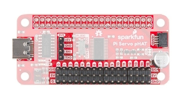
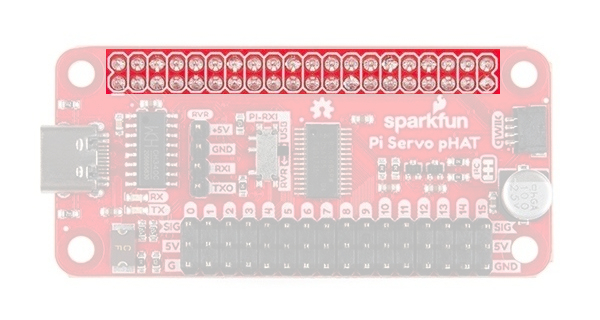
40-Pin Female Header: Power to and/or from the Raspberry Pi is accessed through the 40-pin header. This female header provides several connections to a Raspberry Pi. For power, the 5V pin and 3.3V pins are used.
 The 40-pin GPIO header connection to the Raspberry Pi. Click to enlarge.
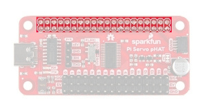
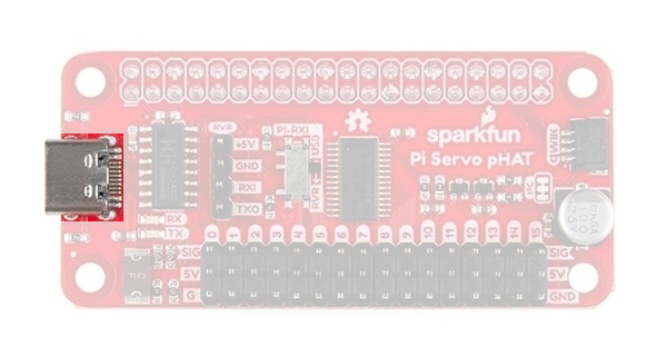
USB-C Connector: This connector can be used to power the servo motors as well as the Raspberry Pi. It can also be used to connect to the Pi via serial port connection (see Serial-UART section below).
 The USB-C connection to the Pi Servo pHAT. Click to enlarge.
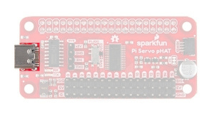
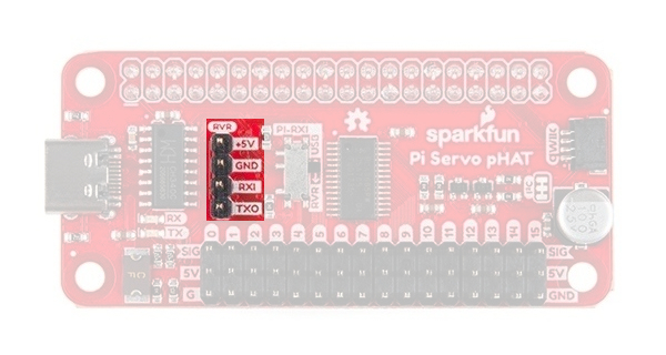
RVR Header: This 4-pin header can be used to power the servo motors as well as the Raspberry Pi. It can also be used to connect to the Pi via serial port connection (see Serial-UART section below).
 The Sphero RVR 4-pin header connection to the Pi Servo pHAT. Click to enlarge.
Power Control & Protection
Although we have attempted to take precautions to guard against reverse current, users should still be wary of what they are doing.
⚡ A short between the 5V and 3.3V lines will permanently put your Raspberry Pi out of commission.
⚡ Power cannot be applied into the 3.3V pin (or Qwiic Connector) from the Servo Pi pHAT. Any application of power to the 3.3V pin of the Raspberry Pi will likely damage it; there is no circuit protection.
- Always calculate your expected and maximum current draw to prevent issues.
⚡ A proper USB port or power supply should be used when providing power through the USB-C connection. A USB 2.0 port supplies a regulated 5V, but is limited to about 500mA. Drawing more current than the USB port on your computer can supply, will most likely cause your computer to freak out and may even damage the power controller.
🔥 Over drawing current from the 3.3V line may strain the 3.3V regulator. The regulator on a Raspberry Pi Zero W will get pretty toasty at 1A.
⚡ The fuse on the USB-C connection is part of the power protection circuitry. Only use use the fuse bypass jumper if you know what you are doing; otherwise, a small mistake could cost you your whole project.
Reverse Current Protection
The Pi Servo pHAT controls 5V power from three different sources, the 5V pin from the 40-pin header of the Raspberry Pi, the 5V pin from the RVR serial connection header, and the USB-C female connector. To provide reverse current protection, the board utilizes circuitry that acts as an ideal diode, a design used on the Raspberry Pi 3 and a requirement for Raspberry Pi hats.
The ideal diode circuit protection prevents back power from the Pi Servo pHAT to either of the USB-C and RVR connections. When using multiple power sources on the Pi Servo pHAT, there is possibility that the power sources will provide conflicting input voltages. If the voltage differential is great enough between the power supplies, a reversal of the flow of power can occur and current pushed back into a power source. This can potentially damage devices, including your computer. For more information, check out the Raspberry Pi Backpowering Guidelines.
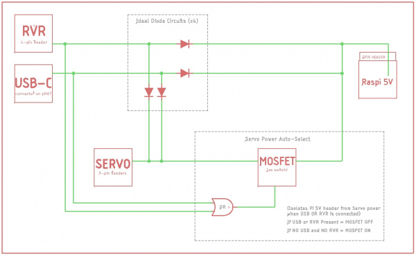
As shown in the functional block diagram above, the USB-C and RVR inputs are both protected against possible back power from either the Raspberry Pi and/or servo power sources with ideal diodes. However, in order to allow power to pass from the Pi Servo pHAT to the Raspberry Pi for a headless setup, power protection or isolation circuitry was't implemented on the 5V GPIO pin. This means that current can freely flow back into the Raspberry Pi to provide power, but may be a concern for the Raspberry Pi Zero, Zero W, 3B+, and 3A+ models, which don't include reverse current protection for their power supplies.
This would be a concern if the 5V power supply on the Raspberry Pi (micro-B USB connector) was somehow sinking current from external power provided through either the USB-C or RVR connections on the Pi Servo pHAT. However, in reality, there still is a small voltage drop across the ideal diodes, the 5V rail on the Raspberry Pi does have some tolerance, and it is not very likely that the power supply on the Raspberry Pi would be sinking current either. In the off chance that you decide to be a mad scientist and test the limits of the boards, there is a power isolation jumper can be manually cut since there is no circuit protection from the 5V line on the Pi Servo pHAT to the 5V line of the Raspberry Pi.
Power Control
Also shown in the functional block diagram above, is a MOSFET acting as an automated switch to manage possible power from the Raspberry Pi. If either the RVR header or the USB-C connector provide 5V, then the power from Raspberry Pi's GPIO header is disconnected from the servo 5V rail. The table below outlines the possible power source combinations.
| Power Sources | Description | ||
|---|---|---|---|
| Pi GPIO | USB-C | RVR Header | |
| X | X | O |
Raspberry Pi powered primarily by own power supply. Servos pull power from USB-C (MOSFET closed; no power from Pi). |
| X | O | X |
Raspberry Pi powered primarily by own power supply. Servos pull power from RVR header (MOSFET closed; no power from Pi). |
| X | X | X |
Raspberry Pi powered primarily by own power supply. Servos pull power from USB-C or RVR header, whichever works best (MOSFET closed; no power from Pi). |
| O | X | X | Raspberry Pi and servos are from USB-C or RVR header, whichever is best. |
| O | O | X | Powered by individual power supplies. |
| O | X | O | |
| X | O | O | |
No outlined in the table is the possibility of power being connected to the servo 5V rail.
USB-C Fuse
On the Pi Servo pHAT there is a fuse (2.5A hold and 5A trip) that limits current draw over the USB-C connection. If more than 5A is drawn, it automatically throttles the current draw and/or disconnects power until the load is removed. A bypass jumper is provided for users who want to remove this limitation; however, users should know what they are doing when using this jumper. As a recommendation, if you do not know what you are doing, you should leave this jumper alone. (see Jumpers section below)
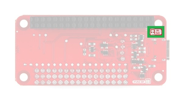
Power Isolation
There is a power isolation jumper connected to the 40-pin GPIO header on the Pi Servo pHAT. This jumper can be cut to isolate the 5V pin of the Raspberry Pi from the 5V used on the Pi Servo pHAT. This is usually used when you expect to be using heavy loads or are worried about noise transferring back to the Raspberry Pi, which often results in intermittent power loss. (see Jumpers section below)
Cutting this jumper does not affect the serial UART connection. However, the jumper does need to be bridged, if you want to power the Raspberry Pi from the Pi Servo pHAT again.
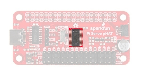
PCA9685
The PCA9685 provides I2C control over the 16-channels of 12-bit pulse width modulation (PWM) on the Pi Servo pHAT. The PCA9685 is designed primarily for LED control, but can be used for other PWM devices like servos.
| Characteristic | Description |
|---|---|
| Operating Voltage (VDD) | 2.3 V to 5.5 V (Hardwired: 5V) |
| Operating Temperature | -40°C to 85°C |
| PWM Outputs |
16 Totem pole outputs (Default: Open-Drain) Sink 25 mA or Source 10 mA (at 5V) Shared PWM frequency Supports hot insertion |
| PWM Frequency | 24Hz to 1526 Hz (Default (1Eh): 200Hz) |
| PWM Resolution | 12-bit (4096 steps of control) |
| Duty Cycle | 0% to 100% (adjustable) |
| Oscillator |
Internal: 25 MHz (Hardwired) External: 50 MHz (max.) input (unavailable) |
| I2C Address |
62 hardware configurable addresses (Hardwired: 0x40) 4 programmable addresses to allow simultaneous groups control of multiple devices:
|
Although, the PWM frequency of all the channels are shared, the duty cycle of the 16 channels of PWM output can be controlled individually. This allows the PCA9685 to control servos or LEDs on each of the outputs. For LEDs, this allows the channels to control or drive the brightness; or the position on servos.
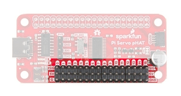
Servo/PWM Headers
The Pi Sevro pHAT can be utilized with various PWM devices, the most typically application will be servos and LEDs. These headers are spaced out to make it easier to attach servo motors to them. Additionally, they are broken out in the standard 3-pin configuration for most hobby-type servo motor connectors.
Serial UART Connections
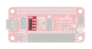
A Raspberry Pi can be interfaced over a serial connection through the Pi Servo pHAT. There are two different access points to the serial UART; the 4-pin header for the Sphero RVR and the USB-C connection. Control over which interface is used is provided by the RX switch on the Pi Servo pHAT.
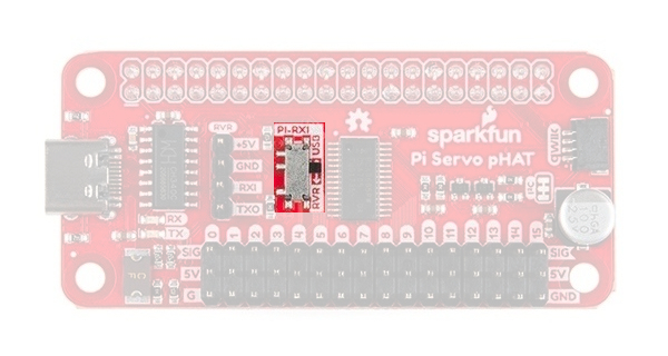
The indication of which connection is used should be straight forward. The interface that is labeled (USB or RVR) on the side that the switch is on (black nub), will indicate the TX connection to the RX pin of the Raspberry Pi for serial communication. As shown in the picture above, the TX line from the USB-C interface is connected to the RX pin of the Raspberry Pi. To change to TX line of the Sphero RVR 4-pin header, users just need to follow the arrow and slide the switch into the RVR position.
For more tips and details on serial communication, read our Serial Communication and Terminal Basics tutorials.
USB-C Connector
This connector can be used for power and to connect to the Pi via serial port connection, to access the Raspberry Pi remotely, without needing to use a monitor and keyboard to set up the Pi (see Headless Raspberry Pi Setup tutorial).
On the Pi Servo pHAT there is a fuse that limit current draw over the USB-C connection. If more than 5A is drawn, it automatically throttles the current draw and/or disconnects power until the load is removed.
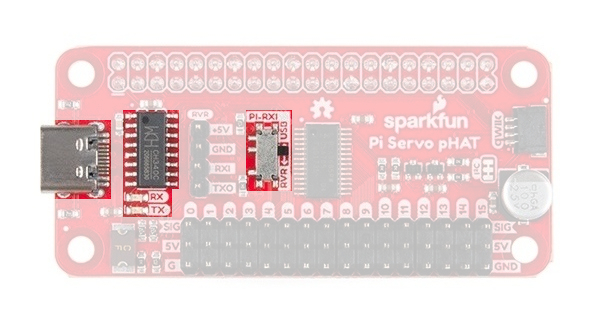
CH340C
The CH340C is a USB-to-Serial adapter from WCH. It is used to convert data to and from USB-C connection to a serial terminal. The driver for the CH340C chip will need to be installed on your computer. We have tested and confirmed that the driver works on Windows 7, Windows 10, Mac OSX High Sierra, and Raspbian Stretch (11-13-2018 release) for the Raspberry Pi. On all operating systems, if you have previously installed the CH340G drivers, you will need to uninstall those drivers first before updating to the new CH340C driver. For more information, check out our How to Install CH340 Drivers Tutorial.
How to Install CH340 Drivers
August 6, 2019
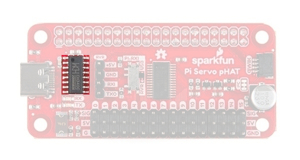
Whenever you send or receive serial data on the USB-C connection, you should seen the RX (yellow) and/or TX (green) LEDs flashing. The RX pin is shares a connection with the 4-pin RVR header and may flash when it is receiving data.
RVR Header
The Sphero RVR requires a 4-pin header to access a Raspberry Pi. On the Pi Servo pHAT we have broken out this connection for a painless integration with the Sphero RVR.

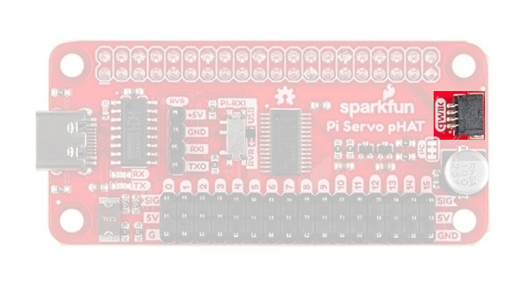
Qwiic Connector
A Qwiic connector is provided for additional compatibility with our Qwiic line of products. The Qwiic system is intended to be a quick, hassle-free cabling/connector system to conveniently add your favorite I2C devices. The Qwiic connector is tied to the I2C pins of the Raspberry Pi and draws power directly from the 3.3V pins.
Jumpers
There are a few jumpers broken out on this board to easily modify a few hardware connections without having to rework individual components. If you are ot sure how to cut a jumper, please read our tutorial here! As a recommendation, please review what each jumper does before making a modification. This is especially true for the fuse bypass jumper, which can have dire consequences.
Power Isolation
This jumper is closed by default. It can be cleared/opened to isolate the power sources on the Pi Servo pHAT from the Pi 5V power rail.
Fuse Bypass
The bypass jumper is provided for users who want to remove the current limitation of the fuse on the USB-C connection; however, users should know what they are doing when using this jumper. The fuse is rated to a 2.5A hold and 5A trip current.
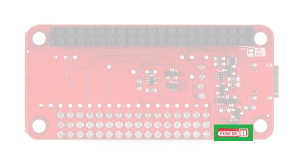
As a recommendation, if you don't know what you are doing, you should leave this jumper alone. The USB-C is capable of delivering tremendous amounts of power and can easily damage hardware.
I2C Pull-Up
Cutting the I2C jumper will disconnect the 10 kΩ pull-up resistors from the I2C bus.
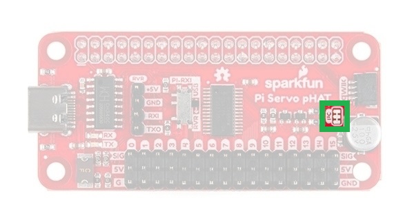
As an example, if you have multiple Qwiic devices with pull-up resistors connected, you may want to cut these jumpers. When there are multiple devices on the I2C bus with pull-up resistors, the equivalent parallel resistance may create too strong of a pull-up for the bus to operate correctly.