Pocket AVR Programmer Hookup Guide
 jimblom,
  bboyho
Programming via Arduino
Arduino has a built-in tool that allows you to upload your sketch via a programmer instead of the serial bootloader. If you're just taking your first steps toward ISP-ing your Arduino-compatible AVR, this is a good place to start.
Connect the Programmer
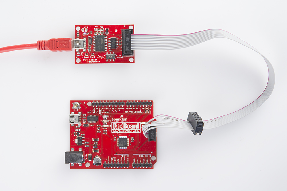
First, let's connect the programmer to our Arduino. Most Arduinos break out the standardized 2x3 ISP header towards the edge of the board. Plug the 2x5-connector end of included programming cable into your AVR Pocket Programmer, then connect the other, 2x3 end into your Arduino.
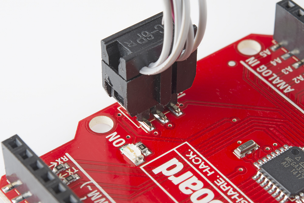
When connecting the programming cable to you Arduino, make sure you match up the polarity! The cable has a "notch" on one side of the plastic housing. This should point towards pin 1 of the Arduino's ISP header. Pin 1 is usually indicated by a stripe next to the hole or pin.
If your Arduino doesn't have the ISP pins populated, check out the bottom section of this page for some tips and tricks we've used through the years.
Powering Target
While connecting your programmer, double-check to make sure the "Power Target" switch is in the correct position. The programmer can power your Arduino alone! If you want it to handle that task, slide it over to the Power Target position.
Unplug your Arduino from USB if you're going to power it via the Programmer -- you don't want to create any ugly reverse current flows through your power sources.
Programming via Arduino
Now that the programmer is connected to your Arduino, open up the IDE. Then open an example sketch like Blink (File > Examples > 1.Basics > Blink).
Before uploading, we need to tell Arduino which programmer we're using. Go up to Tools > Programmer and select USBtinyISP.
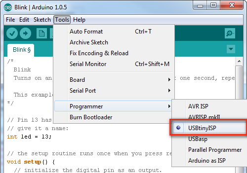
Also make sure you've set the "Board" option correctly! The serial port selection isn't required for uploading the sketch, but is still necessary if you're doing anything with the serial monitor.
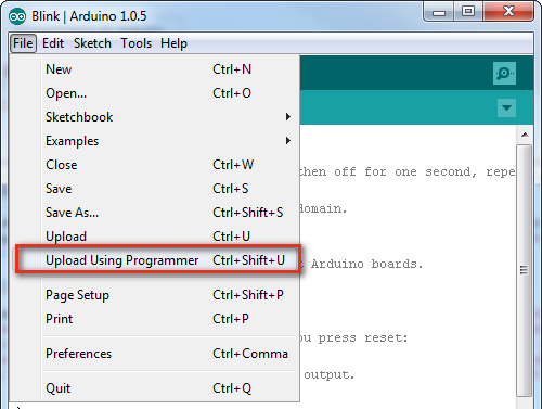
To upload the sketch using the programmer you selected, go to File > Upload Using Programmer. If you'll be doing this a lot, get used to pressing CTRL+SHIFT+U (COMMAND+SHIFT+U on Mac).
The Arduino will run through its normal process of compiling. After the sketch compiles, the Programmer will start lighting up blue everywhere -- the "D+" and "D-" LEDs will light up, and so will the "Stat2" LED. When the "Stat2" LED turns off, the upload will be finished. Check the status area of your Arduino IDE to verify that the sketch is "Done uploading."
If you've uploaded a sketch via the programmer, you've also wiped off the bootloader. If you ever want to put the serial bootloader back on your Arduino, check out the next section.
Programming a Bootloader
The Arduino IDE also has a feature built-in to allow you to (re-)upload a bootloader to the AVR. Here's how:
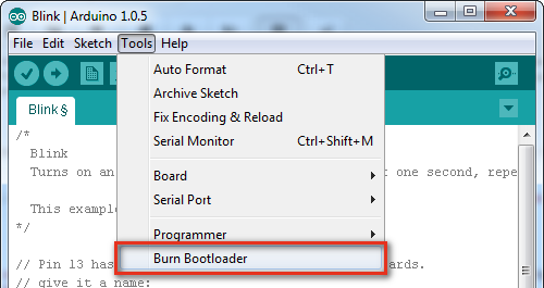
Make sure you've set the Board option correctly -- among other things, that will set which bootloader you'll be uploading. Then, simply navigate up to Tools > Burn Bootloader at the very bottom of the menu.
This process may take a minute-or-so. Not only will the bootloader be written into the flash of your AVR, the fuse bits (setting the clock speed, bootloader space, etc), and lock bits (barring the bootloader from overwriting itself) will also be (re)set.
The bootloader upload process is complete when the "Burning bootloader to I/O board (this may take a minute)..." message turns to "Done burning bootloader". It really does take a while -- it's not lying when it says it "may take a minute."
Pogo Pins or the Angled Header Press
Most Arduino boards should have male pins populated on this 2x3 connector. If your board doesn't have pins shooting out of those holes, there are a few options.
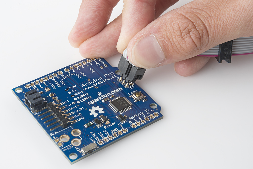
You can solder a couple strips of 3 straight male headers in there, to get the best, most reliable connection. But if you want to avoid soldering, you can use those same headers (long headers work better for this), plugging the long end into the programming cable and pushing the short end into the empty holes, while angling them to make contact on all six pins.
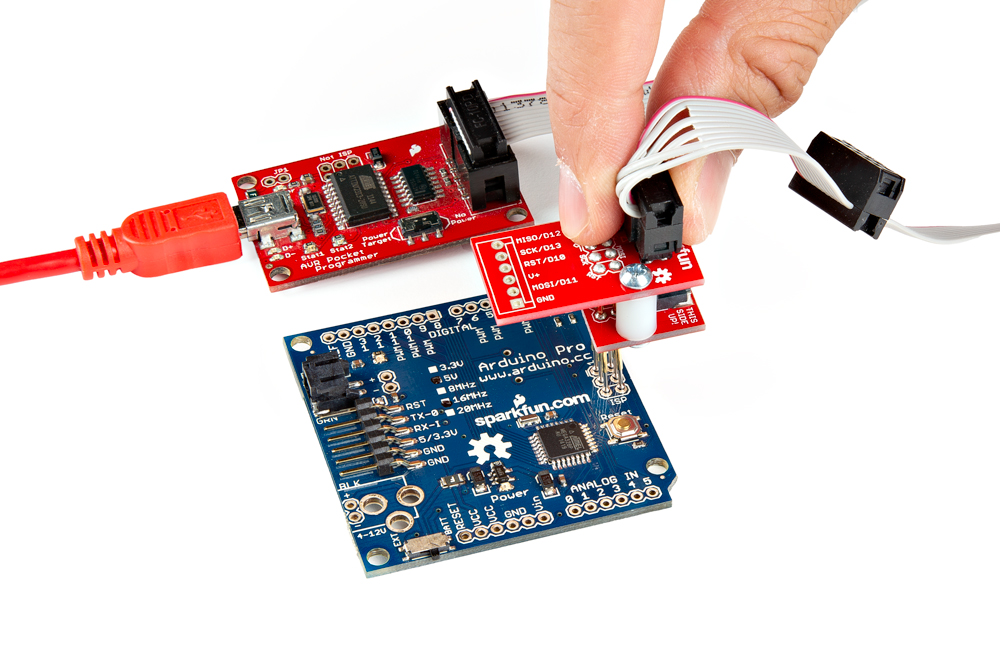
Another solder-less option is to use the ISP Pogo Adapter, which will afford you a more reliable electrical connection.
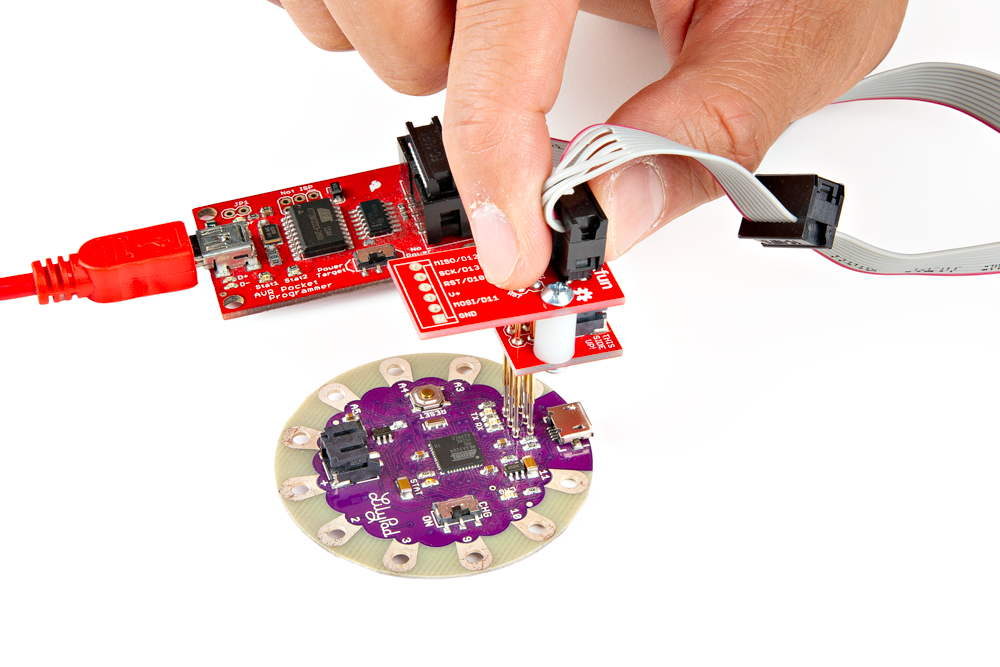
The ISP Pogo Adapter is also great for boards where the ISP programming pins are broken out to small test points such as the LilyPad Arduinos.
Both of these methods can be tricky -- you have to hold those pins steady while the code uploads to your Arduino -- but they're a good solderless, temporary option.