Pro Micro RP2040 Hookup Guide
 bboyho
Hardware Hookup
Header pins were left off the Pro Micro RP2040 to allow users the flexibility of connecting any type of 0.1" header to the board. For temporary connections to the I/O pins, you could use IC hooks to test out the pins. However, you'll need to solder headers or wires of your choice to the board for a secure connection. For advanced users, you could also design a PCB to take advantage of the castellated edges for a lower profile. Here are a few tutorials to connect to the pads depending on your personal preference.
How to Solder: Through-Hole Soldering
September 19, 2013
How to Solder: Castellated Mounting Holes
May 12, 2015
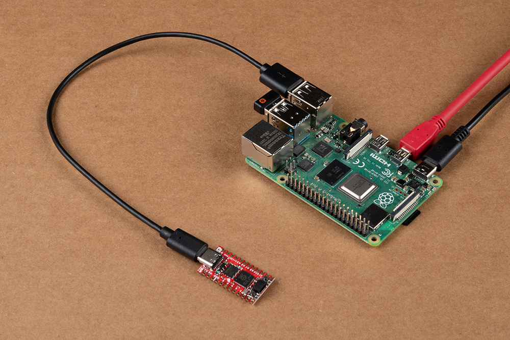
In order to power and upload to the board, you will simply need a USB C cable connected to your computer.
Connecting to GPIO
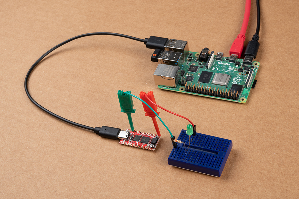
There a few methods of connecting to the GPIO. For a temporary connection when prototyping, you can use IC hooks to connect your circuit to a breadboard. Below is an example of a basic 5mm LED connected to a 330Ω current limiting resistor on a breadboard.
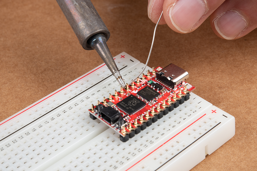
For a secure connection to the Pro Micro RP2040's GPIO, it is recommended to solder header pins. If you designed the board using the footprint, you can also solder the board using the castellated headers. In this case, two 1x12 male header pins are being soldered to the board with the help of a breadboard.
While originally intended to connect Qwiic-enabled devices, you can also use the SDA and SCL pins as a quick, visible test to see if the board is working. In this case, the SCL pin was used as a GPIO pin. Similar to the circuit with the IC hooks, the pin was connected to a basic 5mm LED and a 330Ω current limiting resistor on a breadboard.

Qwiic Enabled Device
You can also easily connect a Qwiic enabled device to the Qwiic connector. Below is an example of the Qwiic VL53L1X distance sensor and Qwiic Micro OLED connected to the Qwiic Pro Micro.
