Processor Interrupts with Arduino
 JordanDee, Ell C
Example: Simple Interrupt
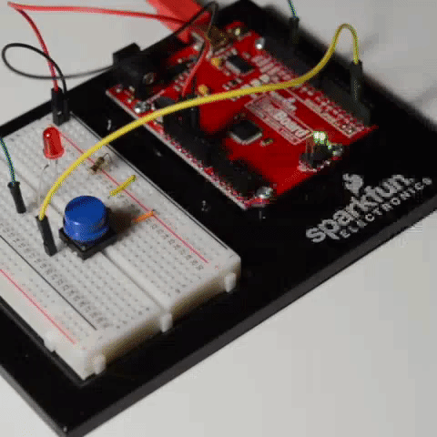
Now that we've got our hardware hooked up, let's look at a simple example that continuously sends an "Off" signal to an LED. We'll attach an interrupt to pin 2; this pin will monitor a button that will send an "On" signal to the LED when pressed and increment a counter.
Most Arduinos have 2 external interrupts built in: interrupt0 (on digital pin 2) and interrupt1 (on digital pin 3). Some boards have more (like the Arduino Mega 2560) - refer to the user manual or datasheet for more information on what your specific board supports. Arduino also has more details on a handful of boards on their attachInterrupt() page. Since we are using a RedBoard here, this example uses pin 2 to monitor for interrupts.
Simple Interrupt Example 1
Select the board and COM port for the RedBoard. Then upload the following.
   /*
    Simple Interrupt Example 1
    by: Jordan McConnell
    SparkFun Electronics
    created on 10/29/11
    */

    int ledPin = 13;  // LED is attached to digital pin 13
    int x = 0;  // variable to be updated by the interrupt

    void setup() {
      //enable interrupt 0 (pin 2) which is connected to a button
      //jump to the increment function on falling edge
      pinMode(ledPin, OUTPUT);
      attachInterrupt(0, increment, RISING);
      Serial.begin(9600);  //turn on serial communication
    }

    void loop() {
      digitalWrite(ledPin, LOW);
      delay(3000); //pretend to be doing something useful
      Serial.println(x, DEC); //print x to serial monitor
    }

    // Interrupt service routine for interrupt 0
    void increment() {
        x++;
        digitalWrite(ledPin, HIGH);
    }
The main loop of this program sends an "OFF" signal to the LED every 3 seconds. Meanwhile, this program watches digital pin 2 (which corresponds to interrupt 0) for a rising edge. In other words, it looks for a voltage change going from logic low (0V) to logic high (5V), which happens when the button is pressed. When this happens the function increment is called. The code within this function is executed, variable x is incremented, and the LED is turned on. Then the program returns to wherever it was in the main loop.
If you play around with it, you'll notice that the LED stays on for seemingly random amounts of time but never longer than 3 seconds. How long the LED stays on depends on where you interrupted the code in the main loop. For example, if the interrupt was triggered right in the exact middle of the delay function, the LED would remain lit for about 1.5 seconds after you hit the button.
Managing Bounce
One common problem with interrupts is they often can trigger multiple times for a single event. When you look at the serial output of the code in example 1, you'll notice that even if you press the button just once, x will increment many times. To explore why this happens, we have to take a look at the signal itself. If we took an oscilloscope to monitor the voltage of the pin at the moment we pressed the button, it would look something like this:
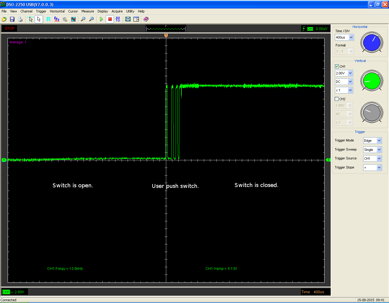
While the main transition of the pin is from low to high, during the process, there are several spikes which can cause multiple interrupts. This is referred to as noise or bounce. A button push might seem like a single step, but in reality the mechanical parts within that button come into contact multiple times before settling into a particular state. There are several ways to remedy this. Often you can fix bounce issues with hardware by adding an appropriate RC filter to smooth the transition. Another option is to address it in software by temporarily ignoring further interrupts for a small time frame after the first interrupt is triggered. Going back to our old example, let's add in a fix that allows the variable x to only be incremented once each button press instead of multiple times.
Simple Interrupt Example 2
Select the board and COM port for the RedBoard if you have not already. Then upload the following.
   /*
    Simple Interrupt example 2
    by: Jordan McConnell
    SparkFun Electronics
    created on 10/29/11
    */

    int ledPin = 13; // LED is attached to digital pin 13
    int x = 0; // variable to be updated by the interrupt

    //variables to keep track of the timing of recent interrupts
    unsigned long button_time = 0;
    unsigned long last_button_time = 0;

    void setup() {
      //enable interrupt 0 which uses pin 2
      //jump to the increment function on falling edge
      pinMode(ledPin, OUTPUT);
      attachInterrupt(0, increment, RISING);
      Serial.begin(9600);  //turn on serial communication
    }

    void loop() {
      digitalWrite(ledPin, LOW);
      delay(3000); //pretend to be doing something useful
      Serial.println(x, DEC); //print x to serial monitor
    }

    // Interrupt service routine for interrupt 0
    void increment() {
      button_time = millis();
      //check to see if increment() was called in the last 250 milliseconds
      if (button_time - last_button_time > 250)
      {
        x++;
        digitalWrite(ledPin, HIGH);
        last_button_time = button_time;
      }
    }
Let's look again at the serial output as you press the button. Open ther serial monitor set at 9600 baud. Note that increment only gets called once for each button press. This fix works because each time the interrupt handler is executed, it compares the current time retrieved by the millis() function with the time the handler was last called. If it's within a certain defined window of time, in this case a fourth of a second, the processor immediately goes back to what it was doing. If not, it executes the code within the if statement updating the variable x, turning on the LED and updating the last_button_time variable so the function has a new value to compare to when it's triggered in the future.
Interrupt Priority Levels
What happens when two interrupts occur at the same time? Most AVRs do not support what we call interrupt priority levels. Should two interrupts occur simultaneously or there are two or more interrupts waiting in a queue, the priority is determined by the order of their vector addresses. Lower vector addresses are serviced first, Reset will take precedence over all interrupt requests. Again, your datasheet will have more information on your specific board.