Programming the pcDuino
This Tutorial is Retired!
This tutorial covers concepts or technologies that are no longer current. It's still here for you to read and enjoy, but may not be as useful as our newest tutorials.
 SFUptownMaker
SPI Communications
The pcDuino has headers exposing two different SPI buses. At this time, however, only one bus, and only one device on that bus, is supported. It's possible to use other GPIO pins to add slave select lines, of course, with a hit to performance.
Hardware
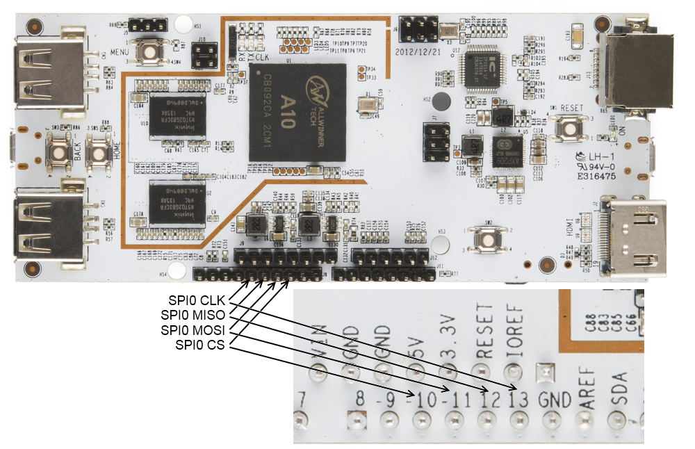
The currently available SPI peripheral, SPI0, can be accessed through four of the pins on the Arduino-compatible headers along the bottom edge of the board. These pins break out the MOSI, MISO, SCK, and CS lines from the processor, allowing full hardware peripheral support of SPI communications.
SPI programming in C++
If you've been following along with the tutorial, a lot of this stuff should look familiar. Open a file descriptor for the spidev0.0 device, then use ioctl() to pass settings (defined in /linux/spi/spidev.h) to the peripheral. Actual message passing is a bit messy, though: you need to create a structure, then pass that structure to the file descriptor via ioctl().
We'll be using the ADXL362 accelerometer breakout board as a test device in this code.
Don't forget to use the pin mode files that we talked about back in the GPIO section to set the pins to SPI mode!
#include <stdio.h>
#include <unistd.h>
#include <fcntl.h>
#include <string.h>
#include <sys/ioctl.h>
#include <linux/spi/spidev.h>
#include "spi_test.h"

static const char *spi_name = "/dev/spidev0.0";

int main(void)
{
  int res = 0;  // We can use this to monitor the results of any operation.

  // The very first thing we need to do is make sure that the pins are set
  //   to SPI mode, rather than, say, GPIO mode.
  char path[256];

  for (int i = 10; i<=13; i++)
  {
    // Clear the path variable...
    memset(path,0,sizeof(path));
    // ...then assemble the path variable for the current pin mode file...
    sprintf(path, "%s%s%d", GPIO_MODE_PATH, GPIO_FILENAME, i);
    // ...and create a file descriptor...
    int pinMode = open(path, O_RDWR);
    // ...which we then use to set the pin mode to SPI...
    setPinMode(pinMode, SPI);
    // ...and then, close the pinMode file.
    close(pinMode);
  }

  // As usual, we begin the relationship by establishing a file object which
  //   points to the SPI device.
  int spiDev = open(spi_name, O_RDWR);

  // We'll want to configure our SPI hardware before we do anything else. To do
  //   this, we use the ioctl() function. Calls to this function take the form
  //   of a file descriptor, a "command", and a value. The returned value is
  //   always the result of the operation; pass it a pointer to receive a value
  //   requested from the SPI peripheral.

  // Start by setting the mode. If we wanted to *get* the mode, we could
  //   use SPI_IOC_RD_MODE instead. In general, the "WR" can be replaced by
  //   "RD" to fetch rather than write. Also note the somewhat awkward
  //   setting a variable rather than passing the constant. *All* data sent
  //   via ioctl() must be passed by reference!
  int mode = SPI_MODE0;
  ioctl(spiDev, SPI_IOC_WR_MODE, &mode);

  // The maximum speed of the SPI bus can be fetched. You'll find that, on the
  //  pcDuino, it's 12MHz.
  int maxSpeed = 0;
  ioctl(spiDev, SPI_IOC_RD_MAX_SPEED_HZ, &maxSpeed);
  printf("Max speed: %dHz\n", maxSpeed);

  // In rare cases, you may find that a device expects data least significant
  //   bit first; in that case, you'll need to set that up. Writing a 0
  //   indicates MSb first; anything else indicates LSb first.
  int lsb_setting = 0;
  ioctl(spiDev, SPI_IOC_WR_LSB_FIRST, &lsb_setting);

  // Some devices may require more than 8 bits of data per transfer word. The
  //   SPI_IOC_WR_BITS_PER_WORD command allows you to change this; the default,
  //   0, corresponds to 8 bits per word.
  int bits_per_word = 0;
  ioctl(spiDev, SPI_IOC_WR_BITS_PER_WORD, &bits_per_word);

  // Okay, now that we're all set up, we can start thinking about transferring
  //   data. This, too, is done through ioctl(); in this case, there's a special
  //   struct (spi_ioc_transfer) defined in spidev.h which holds the needful
  //   info for completing a transfer. Its members are:
  //    * tx_buf - a pointer to the data to be transferred
  //    * rx_buf - a pointer to storage for received data
  //    * len - length in bytes of tx and rx buffers
  //    * speed_hz - the clock speed, in Hz
  //    * delay_usecs - delay between last bit and deassertion of CS
  //    * bits_per_word - override global word length for this transfer
  //    * cs_change - strobe chip select between transfers?
  //    * pad - ??? leave it alone.

  // For this example, we'll be reading the address location of an ADXL362
  //   accelerometer, then writing a value to a register and reading it back.
  //   We'll do two transfers, for ease of data handling: the first will
  //   transfer the "read register" command (0x0B) and the address (0x02), the
  //   second will dump the response back into the same buffer.

  struct spi_ioc_transfer xfer;
  memset(&xfer, 0, sizeof(xfer));
  char dataBuffer[3];
  char rxBuffer[3];
  dataBuffer[0] = 0x0B;
  dataBuffer[1] = 0x02;
  dataBuffer[2] = 0x00;
  xfer.tx_buf = (unsigned long)dataBuffer;
  xfer.rx_buf = (unsigned long)rxBuffer;
  xfer.len = 3;
  xfer.speed_hz = 500000;
  xfer.cs_change = 1;
  xfer.bits_per_word = 8;
  res = ioctl(spiDev, SPI_IOC_MESSAGE(1), &xfer);
  printf("SPI result: %d\n", res);
  printf("Device ID: %d - %d - %d\n", rxBuffer[2], rxBuffer[1], rxBuffer[0]);
}

void setPinMode(int pinID, int mode)
{
  writeFile(pinID, mode);
}

// While it seems okay to only *read* the first value from the file, you
//   seemingly must write four bytes to the file to get the I/O setting to
//   work properly. This function does that.
void writeFile(int fileID, int value)
{
  char buffer[4];  // A place to build our four-byte string.
  memset((void *)buffer, 0, sizeof(buffer)); // clear the buffer out.
  sprintf(buffer, "%d", value);
  lseek(fileID, 0, SEEK_SET);   // Make sure we're at the top of the file!
  int res = write(fileID, buffer, sizeof(buffer));
}
SPI Programming in Python
Fortunately, a nice package exists for making SPI more accessible in Python. Unfortunately, installing it is difficult--much more so than the packages for I2C or serial. Here are the instructions to follow:
Update your package list for apt-get. In a terminal, type
sudo apt-get updateThis will update the list of packages available to the apt-get program, ensuring that you get the right versions of the things we'll be installing next.
Install git. Git is a source control tool used for version tracking, and it's extremely useful. The SPI package in question resides on GitHub, which is a web portal for sharing git projects. To install git, pull up a terminal window and type
sudo apt-get install gitThis installs the git toolchain; you don't really need to know how to use it for what we're doing here, but if you're interested, we have a git tutorial that will teach you a lot of what you need to know.
Install python-dev. This is adds to python the ability to develop C-based extensions. To install, open a terminal window (or use the one that was open from installing git) and type
sudo apt-get install python-devClone the SPI-Py git repository. This is the source code for the SPI python library we'll be using. The command to type is
git clone https://github.com/lthiery/SPI-Py.gitInstall the SPI-Py module. Type
cd SPI-Py
sudo python setup.py install
Now you're set up and ready to write some code! Here's a very simple Python app that will do essentially the same thing as the C++ code above does--connect to an ADXL362 and check the device ID register.
#!/usr/bin/env python

import spi

## The openSPI() function is where the SPI interface is configured. There are
##   three possible configuration options, and they all expect integer values:
##   speed - the clock speed in Hz
##   mode - the SPI mode (0, 1, 2, 3)
##   bits - the length of each word, in bits (defaults to 8, which is standard)
## It is also possible to pass a device name, but the default, spidev0.0, is
##   the only device currently supported by the pcDuino.

spi.openSPI(speed=1000000, mode=0)

## Data is sent as a tuple, so you can construct a tuple as long as you want
##   and the result will come back as a tuple of the same length.
print spi.transfer((0x0B, 0x02, 0x00))

## Finally, close the SPI connection. This is probably not necessary but it's
##   good practice.
spi.closeSPI()