Qwiic Pro Micro USB-C (ATmega32U4) Hookup Guide
 bboyho
Hardware Hookup
Header pins were left off the Qwiic Pro Micro to allow users the flexibility of connecting any type of 0.1" header to the board. For temporary connections to the I/O pins, you could use IC hooks to test out the pins. However, you'll need to solder headers or wires of your choice to the board for a secure connection. For advanced users, you could also design a PCB to take advantage of the castellated edges for a lower profile. Here are a few tutorials to connect to the pads depending on your personal preference.
How to Solder: Through-Hole Soldering
September 19, 2013
How to Solder: Castellated Mounting Holes
May 12, 2015
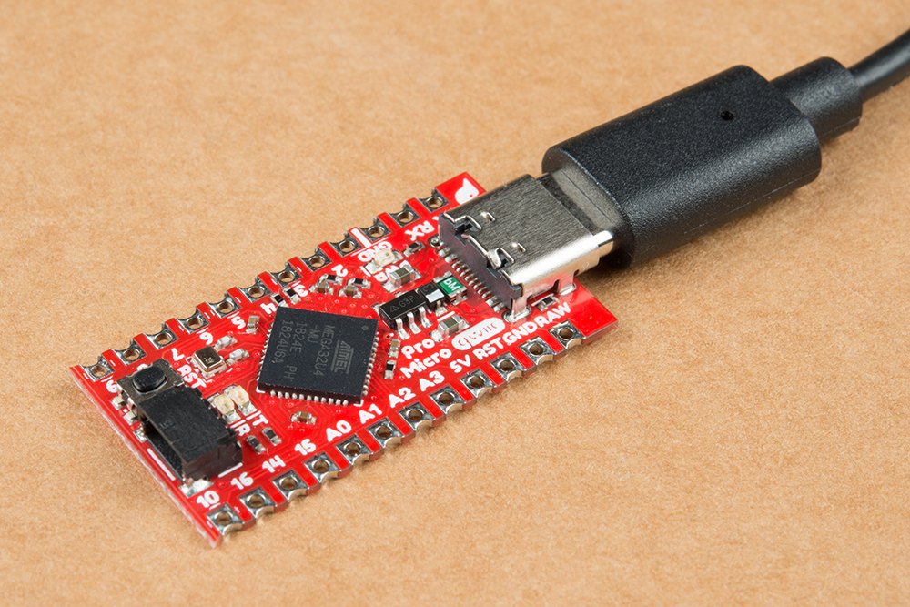
In order to power and upload to the board, you will simply need a USB C cable connected to your computer. For the scope of this tutorial, you'll get as far as example 1.
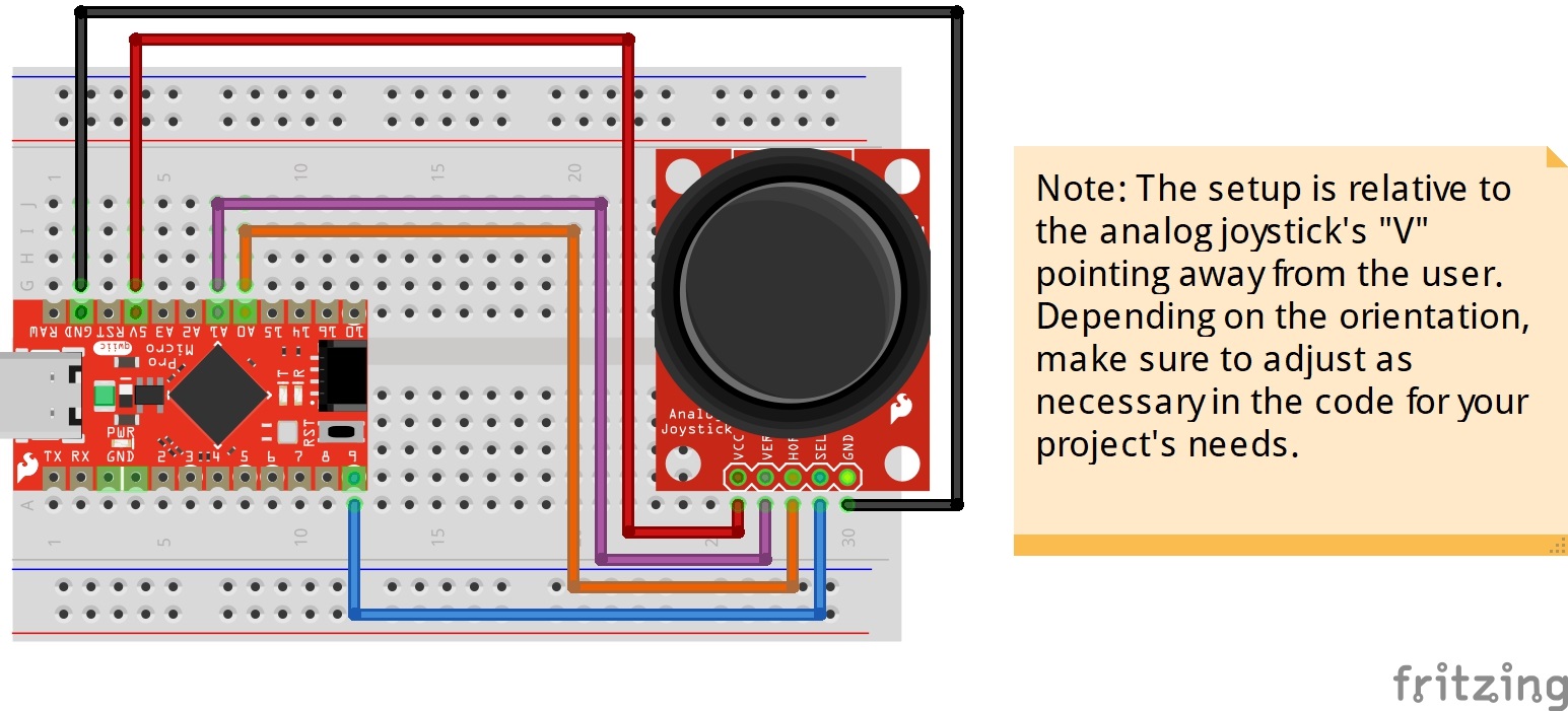
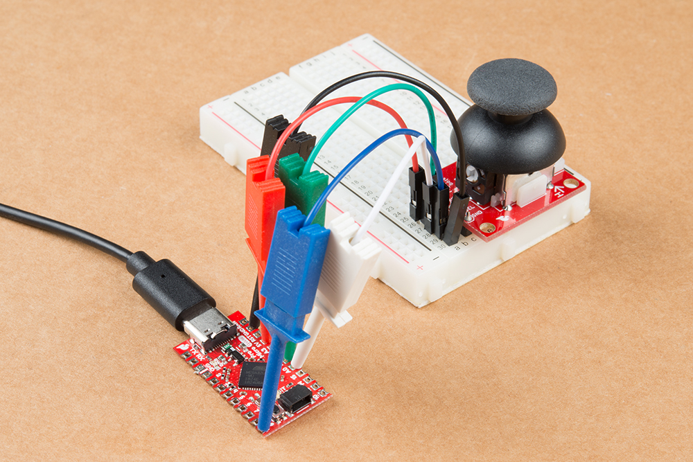
To take advantage of the board's HID, we recommend some sort of input. The analog joystick provides a few inputs to test our the keyboard and mouse in example 2.
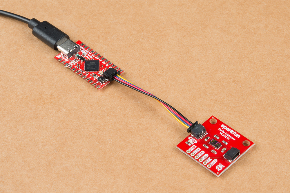
Qwiic Enabled Device
You can also easily connect a Qwiic enabled device to the Qwiic connector. Below is an example of a distance sensor connected to the Qwiic Pro Micro. If you have an installation with a kiosk's screensaver turned on, you could use the Qwiic Pro Micro to wake it up by moving a mouse if there is someone within a certain distance of the VL53L1X sensor.