Qwiic Single Relay Hookup Guide
 Englandsaurus
Hardware Overview
First let's check out some of the characteristics listed in the relay's datasheet that we're dealing with, so we know what to expect out of the board.
| Characteristic | Range |
|---|---|
| Operating Voltage | 1.7V-3.6V |
| Supply Current | 100mA |
| Coil Resistance | 23.5Ω |
| I2C Address | 0x18 (Default), (Jumper changes to 0x19) |
| Max Current (Through Relay) | 5.5A (240 VAC) |
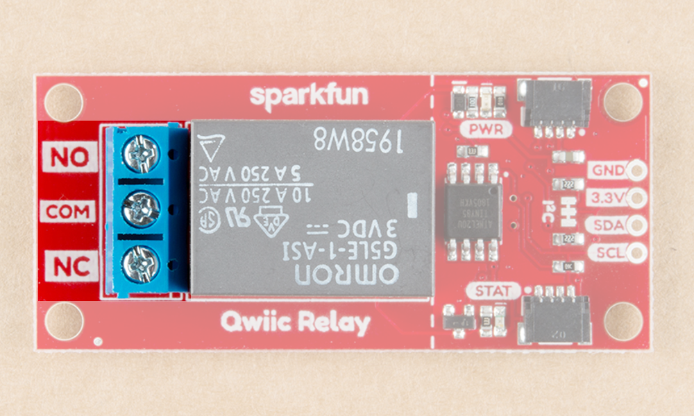
Pins
The following table lists all of the relay's pins and their functionality.
| Pin | Description | Direction |
|---|---|---|
| GND | Ground | In |
| 3.3V | Power | In |
| SDA | Data | Bi-directional |
| SCL | Clock | In |
| NC | Normally Closed | Switch |
| NO | Normally Open | Switch |
| COM | Switch Common | Switch |
Optional Features
The Qwiic Relay has pull up resistors attached to the I2C bus; if multiple sensors are connected to the bus with the pull-up resistors enabled, the parallel equivalent resistance will create too strong of a pull-up for the bus to operate correctly. As a general rule of thumb, disable all but one pair of pull-up resistors if multiple devices are connected to the bus. If you need to disconnect the pull up resistors they can be removed by cutting the traces on the corresponding jumpers highlighted below.

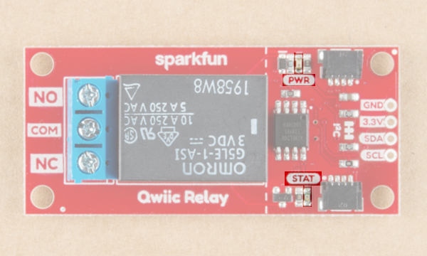
The Power LED will light up when the board is powered. The Status LED will light up when the relay has been triggered and the switch is closed, both are highlighted in the below image
The onboard screw terminal should be used to connect your high-power load, it is highlighted below. The middle COM pin should be hooked up to the Live wire (Usually black) coming from the wall, while NO or NC should be connected to the Live wire on the device side of things.