Raspberry gPIo
Contributors:
 jimblom,
  MTaylor
jimblom, MTaylor Hardware Setup
To get a head start you can assemble the circuit now. We'll use this setup for both the C and Python examples. We'll use two LEDs to test the output functionality (digital and PWM), and a button to test the input.
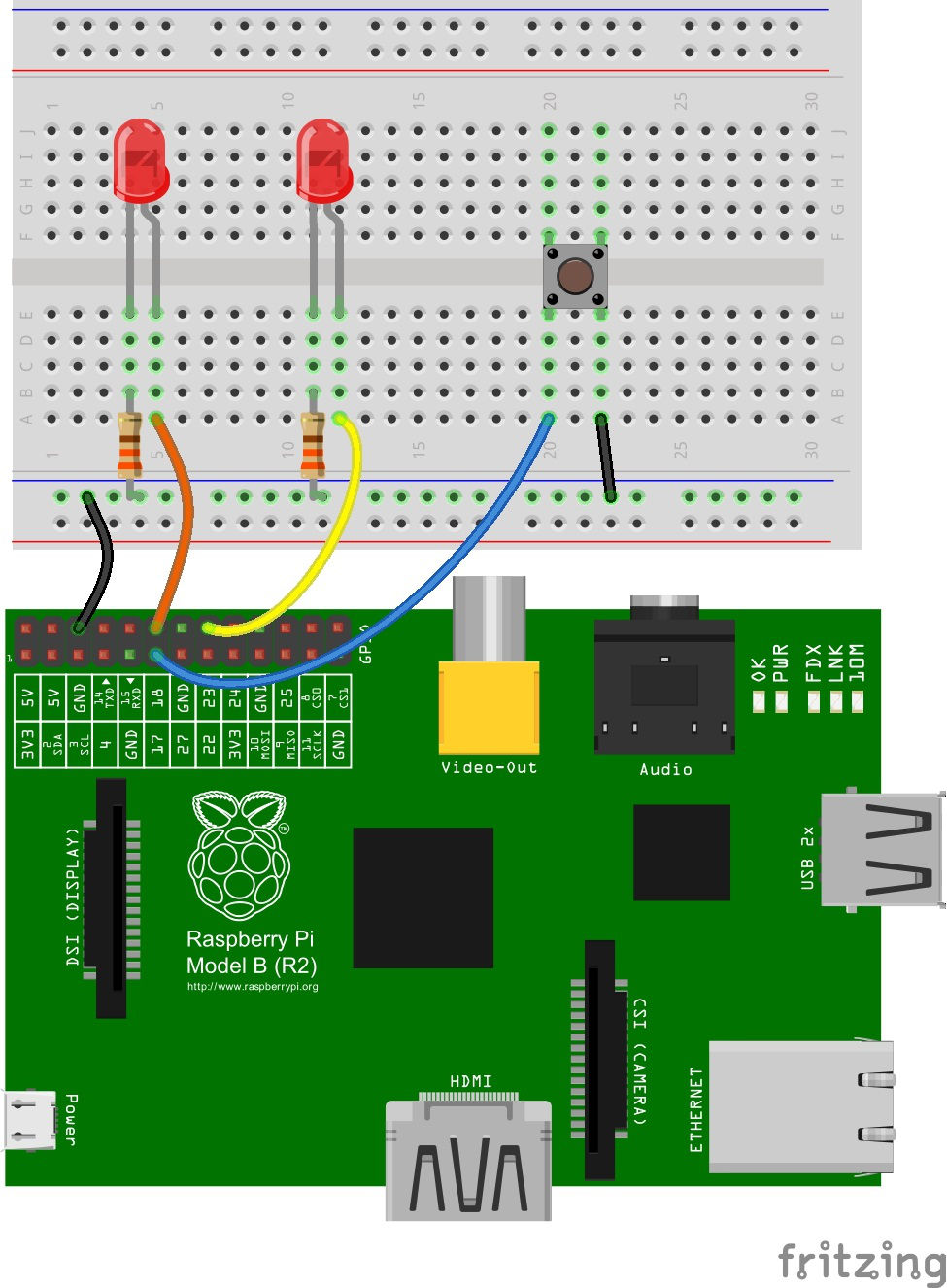
Connections to Original Pi
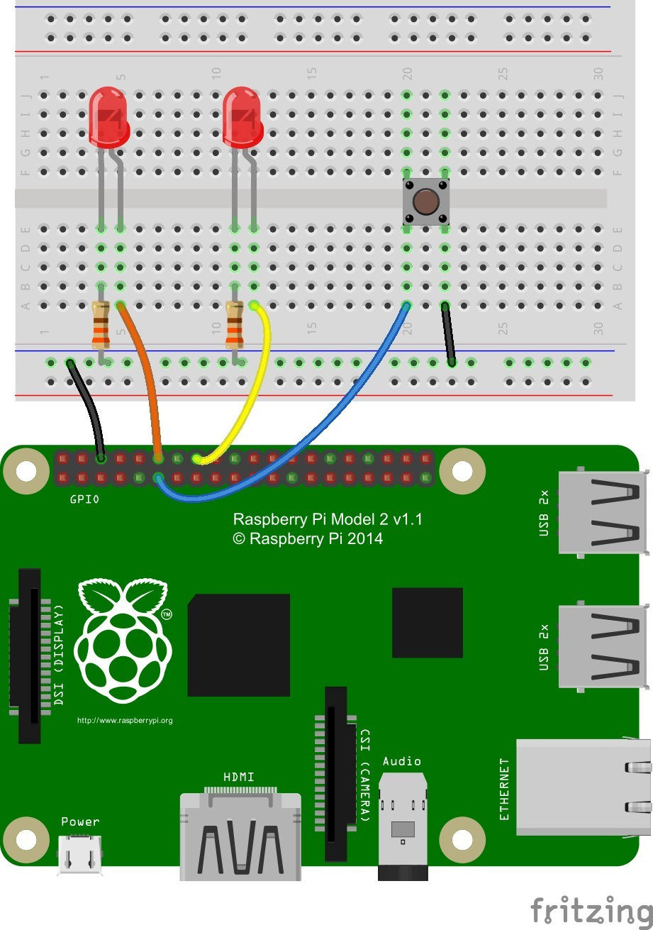
Connections to the Pi B + and Pi 2 B
Our two LEDs are connected to the Pi's GPIO 18 and GPIO 23 -- those are the Broadcom chip-specific numbers. If you're basing your wiring off the P1 connector pin numbers, that'd be pins 12 and 16.
The button is connected to Broadcom GPIO 17, aka P1 pin 11.
If you have Pi Wedge, the hookup should be pretty straight-forward. It'll look a little something like this when you're done:
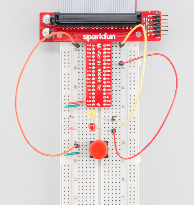
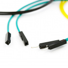
If you don't have a Pi Wedge, male-to-female jumper wires help to make an easy transition from Pi to breadboard.
