Raspberry Pi Zero Helmet Impact Force Monitor
 jenfoxbot
Build it: Electronics!
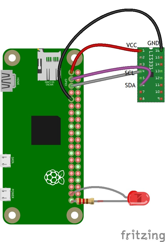
Here's the electrical schematic for this project:
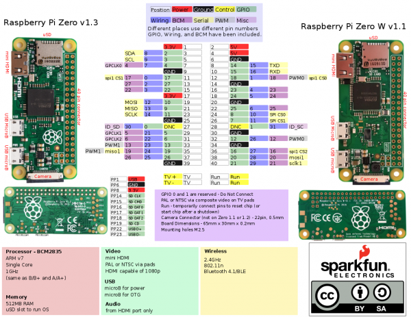
Here's the pinout for the Pi Zero W for reference:
Connect the LIS331 Accelerometer to the Pi's GPIO
Solder and carefully remove any flux residue on the accelerometer and Pi GPIO's header pins.
 |
 |
Then connect jumper wires between the LIS331 breakout board and Pi between the following pins:
| LIS331 Breakout Board | Raspberry Pi GPIO Pin |
|---|---|
| GND | GPIO 9 (GND) |
| VCC | GPIO 1 (3.3V) |
| SDA | GPIO 3 (SDA) |
| SCL | GPIO 5 (SCL) |
To make it easier to connect the sensor to the Pi Zero, a custom adapter was made by using a female header and jumper wires. Heat shrink was added after testing the connections.

Add an Alert LED!
Solder a current limiting resistor to the negative LED leg (shorter leg) and add shrink wrap (or electrical tape) for insulation.
 |
 |
Use two jumper cables or header pins to connect the positive LED leg to GPIO26 and the resistor to GND (header positions 37 and 39, respectively).
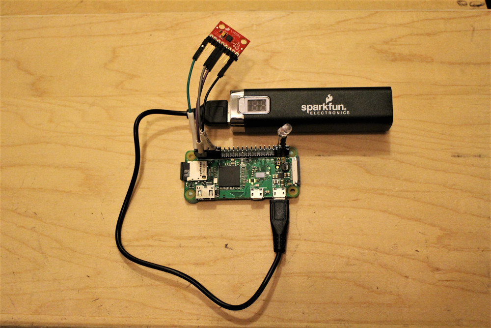
Completed Setup
Connect the battery pack to the Pi's input power to complete the setup!