RedBot Assembly Guide
This Tutorial is Retired!
This tutorial covers concepts or technologies that are no longer current. It's still here for you to read and enjoy, but may not be as useful as our newest tutorials.
 SFUptownMaker,
  HelloTechie
Jumper Wires
It will make it easier to connect the sensors to the RedBot mainboard later if you add the jumper wires to the Line Followers and Wheel Encoder (if you installed in earlier) now, before screwing down the top chassis piece.
Locate the following:
- 1x Bottom Chassis Piece
- 13x Jumper Wires
Connecting the Line Followers
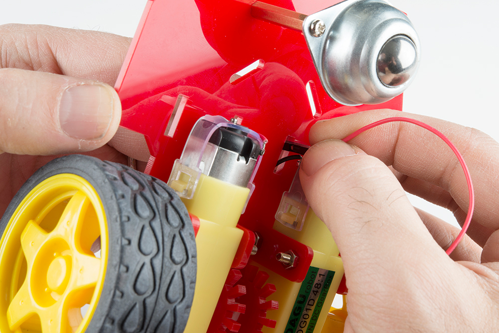
The motors already have wires, so you won't have to add more jumper wires. You will need to place the motor jumper wires through the chassis's openings.
Connect one end of the jumper wires to each one of the Line Followers' header pins. Keep in mind you are able to use any jumper wire colors. However, following along with the jumper wire colors this assembly guide may be helpful if this is your first time assembling the RedBot. See below if you are following along with the jumper wire colors to help lessen confusion when hooking up to the RedBot Mainboard later in the guide.
Left RedBot Sensor - Line Follower → Color Jumper Wire
- GND → Black
- VCC → Red
- OUT → Yellow
Middle RedBot Sensor - Line Follower → RedBot Mainboard
- GND → Black
- VCC → Red
- OUT → Blue
Right RedBot Sensor - Line Follower → RedBot Mainboard
- GND → Black
- VCC → Red
- OUT → Green
Make sure to push the jumper wires in all the way.
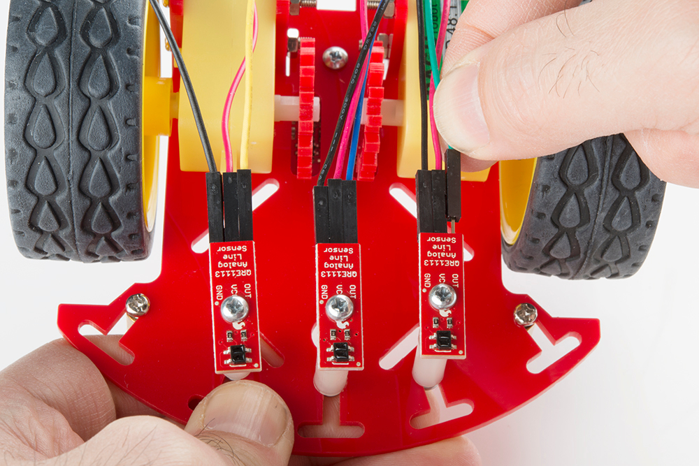
Stick the Line Followers' jumper wires through the top of the bottom chassis piece.

**If you did not install the Wheel Encoders, you can skip the rest of this section. **
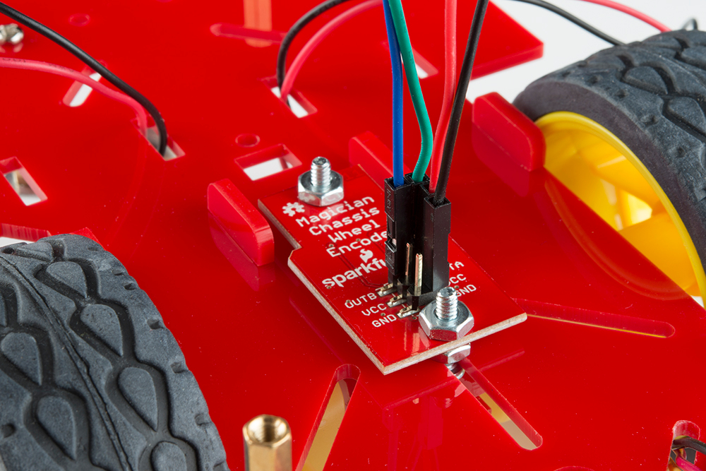
Connecting the Wheel Encoder
Add four jumper wires to the RedBot Sensor - Wheel Encoder. There should be a jumper wire each one of the following pins: OUTB, OUTA, VCC, and GND. See below if you are following along with the jumper wire colors to help lessen confusion when hooking up to the RedBot Mainboard later in the guide. Remember that the color of the jumper wire doesn't matter, and this is only to be helpful in knowing which jumper wires go to which pins.
RedBot Sensor - Wheel Encoder → RedBot Mainboard
- OUTB → Blue
- OUTA → Green
- VCC → Red
- GND → Black