RedBot Assembly Guide Rev 02
This Tutorial is Retired!
This tutorial covers concepts or technologies that are no longer current. It's still here for you to read and enjoy, but may not be as useful as our newest tutorials.
 HelloTechie,
  SFUptownMaker
Motors
In this section, you will be placing the two motors on the bottom side of the bottom chassis piece.
Locate the Following:
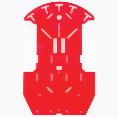
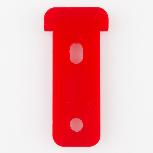
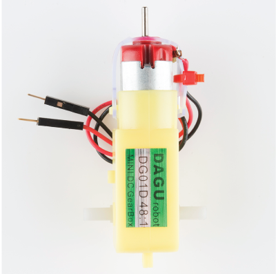
| 1x Bottom Chassis Piece | 4x Motor Holder | 2x Motor |
 |
 |
 |
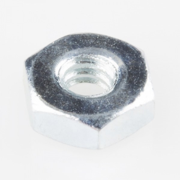
| 2x 4-40 x 1 1/4" Flat Head Screw | 2x 4-40 Hex Nut | |
 |
 |
Please note: ** Pay close attention to which screws you are using. There are two different screws in the RedBot Kit. (30x** of the 4-40 x 1/4" Phillips screw and 4x of the 4-40 x 1 1/4" flat head screw).
Adding the RedBot Sensor - Mechanical Bumper? You will have 3x of the 4-40 x ⅜" Phillips screw.
Adding the Motors
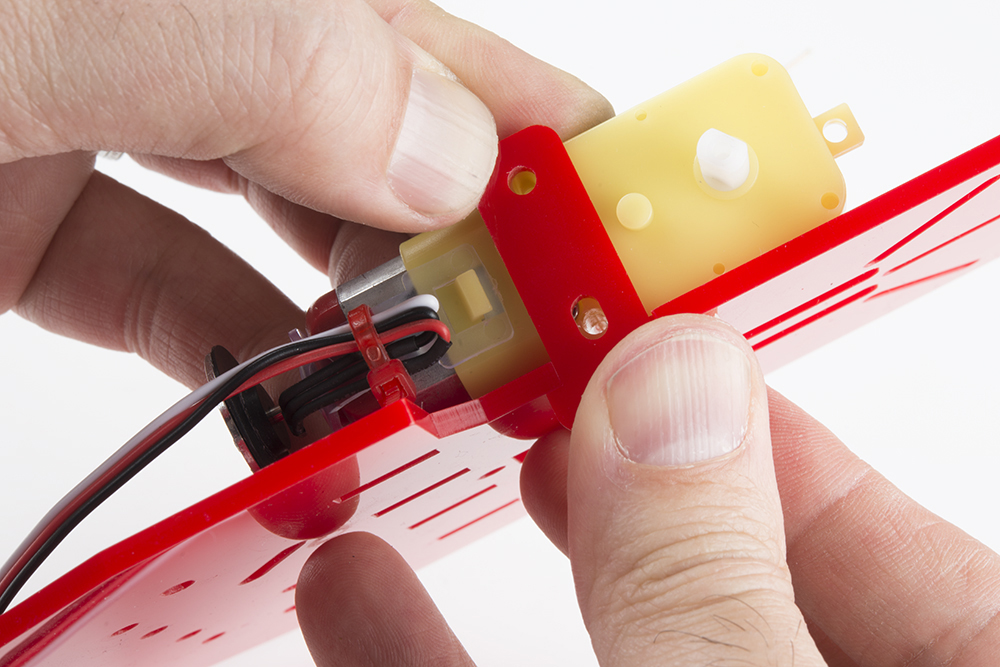
Find the correct location on the bottom chassis piece.
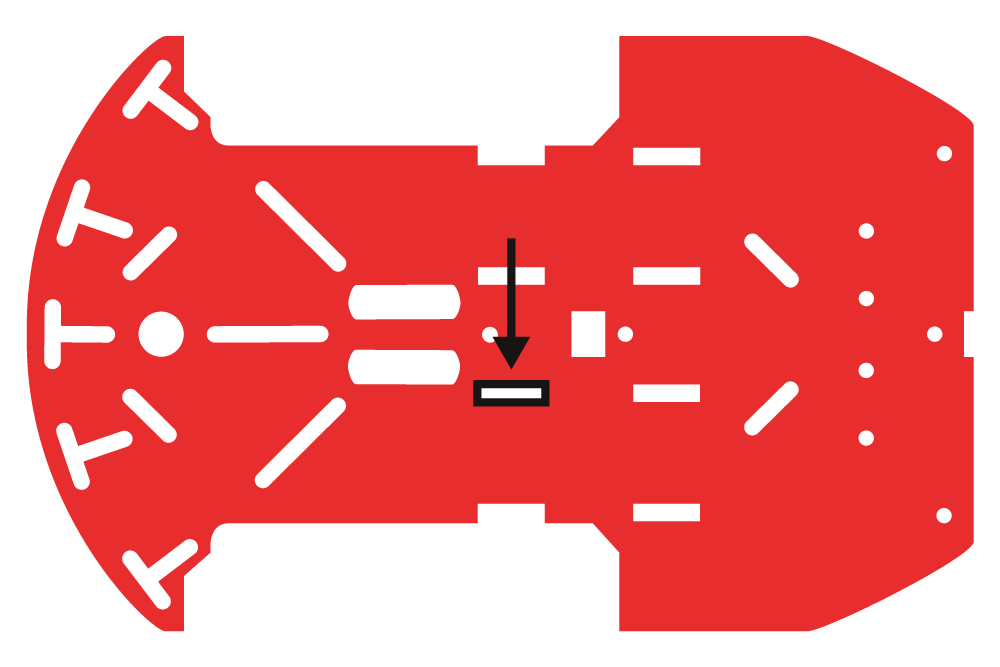
Place one of the motor holders through the chassis at that location.
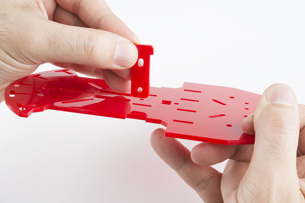
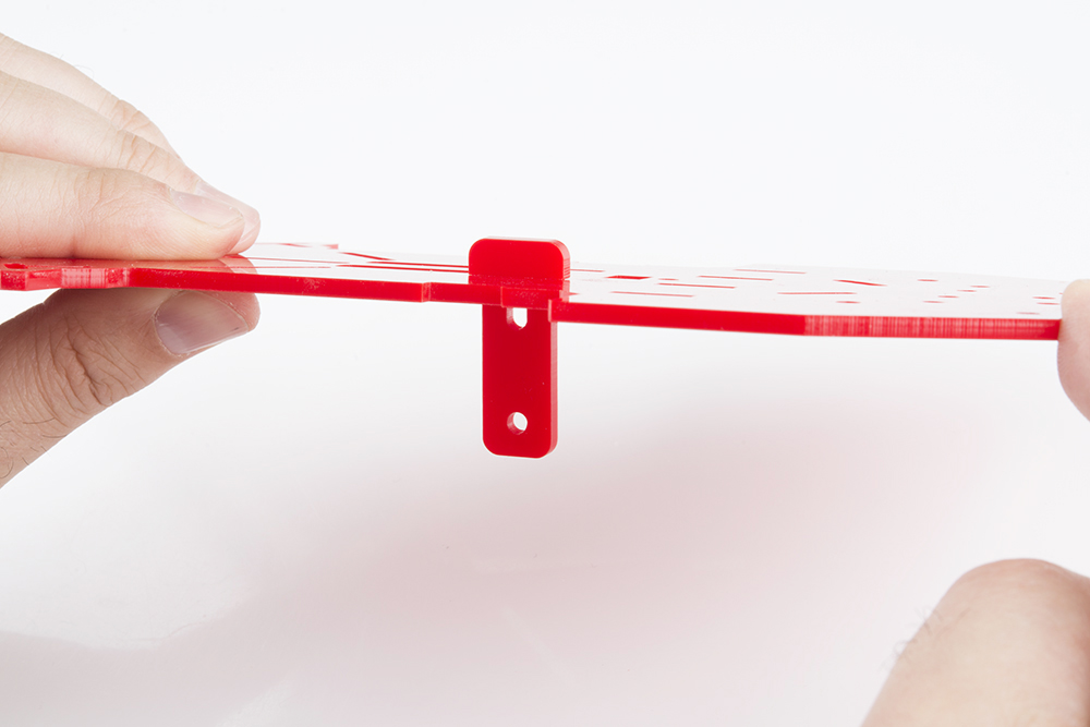
Push the motor holder all the way down.
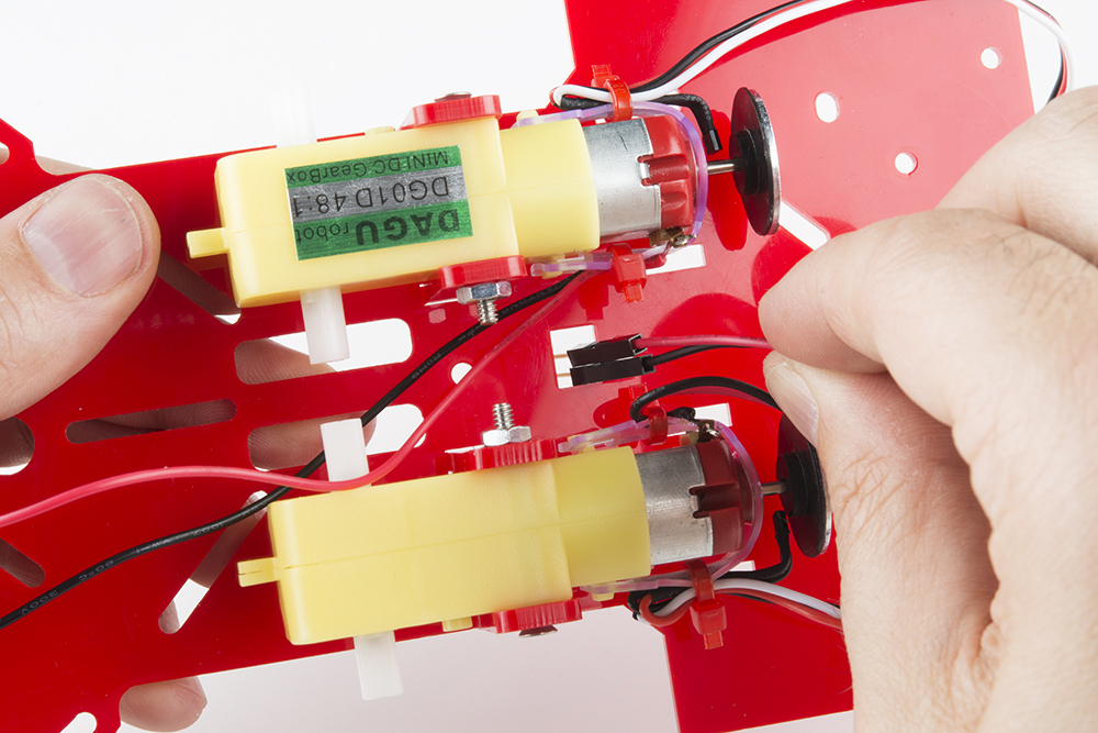
Place the first motor on the bottom side of the chassis piece. It is important to make sure the side of the motor with the wheel encoder is pointing to the back side of the RedBot bottom chassis piece. To tell the difference between the back and front of the chassis, the chassis's back is flat and the chassis's front is curved. (The back of the chassis is where the metal ball caster will go. You will be putting that on later.)
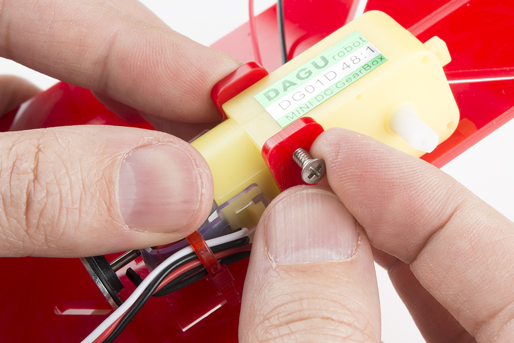
Line up the two motor holes with the two motor holder holes. Make sure that the red wire soldered onto the motor is on top and away from the chassis piece.
Place the 4-40 x 1 1/4" flat head screw through the top motor holder and motor holes.
Using a screwdriver and 4-40 hex nut, tighten the screw.
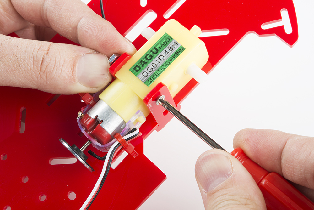
Double check the side of the motor with the wheel encoder is pointing to the back side of the RedBot bottom chassis piece.
Following the same steps as the first motor, add the second motor holder on the other side.
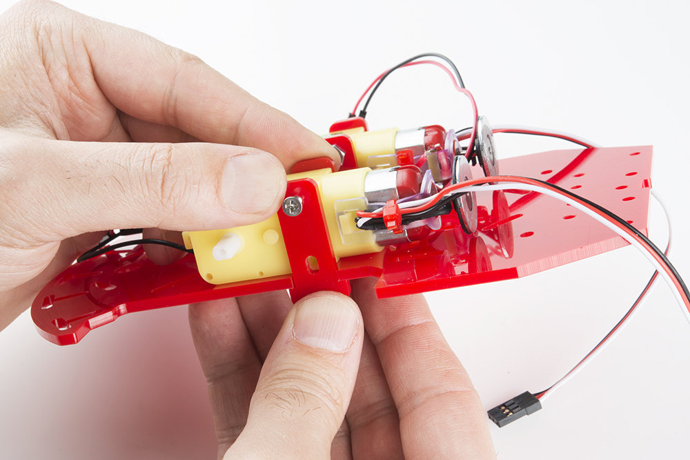
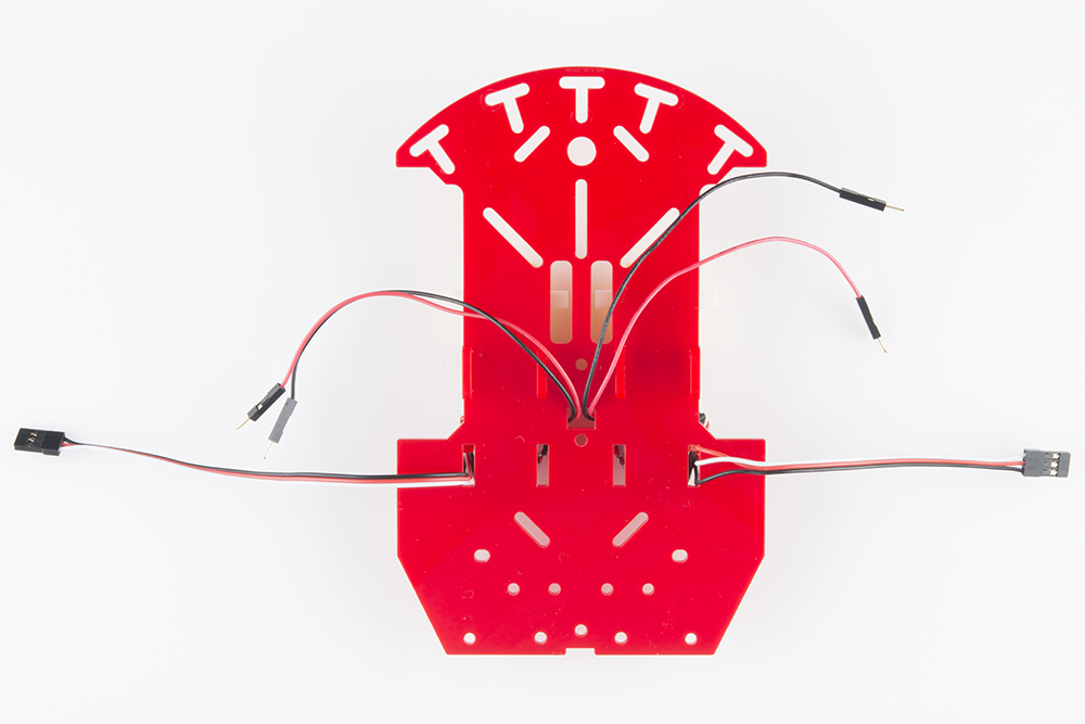
Place the motor's black and red wires through the bottom chassis so the wires come through to the top side of the chassis.
Now, push the wheel encoder's wires through to the top side of the chassis. It is best to push through the chassis opening that is closest to the motor, as shown below.

As you can see, the wires are now through the top of the chassis piece. It is highly recommended to have the wires push through the same chassis openings as shown below. This way it is easier to connect to the RedBot Mainboard toward the end.