Retired - Electric Imp Breakout Hookup Guide
This Tutorial is Retired!
An electric imp hug! Provides an overview of the imp card and breakout. Both hardware and firmware subjects are covered.
View the updated tutorial: Retired - Electric Imp Breakout Hookup Guide v2
 jimblom
Example 1: I/O Control
The electric imp can do most anything an Arduino or similar microcontroller can. It's got analog-to-digital converters, PWM, SPI, I2C, UARTs, and it even has digital-to-analog converters. In this first snippet of example code, we'll show off the basics of I/O control -- digital and anlog input/output.
Using the Planner
After sending the BlinkUp and commissioning your imp, it should show up in your planner as a lone, blue rectangle. The word "Blank" will appear in the box. The box's name will reflect the code that the imp is running.
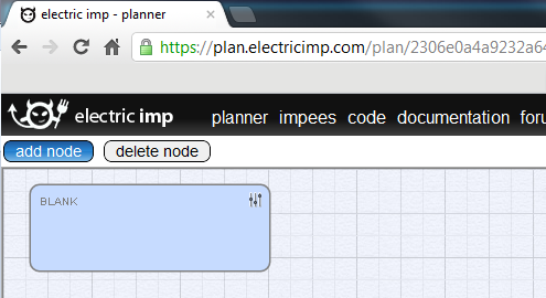
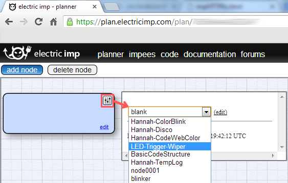
To upload code to the imp, you need to click the "slider" icon in the top-right of the blue box, and select the code you wish to stick on there. I guess that means we need some code then?!
Example Code
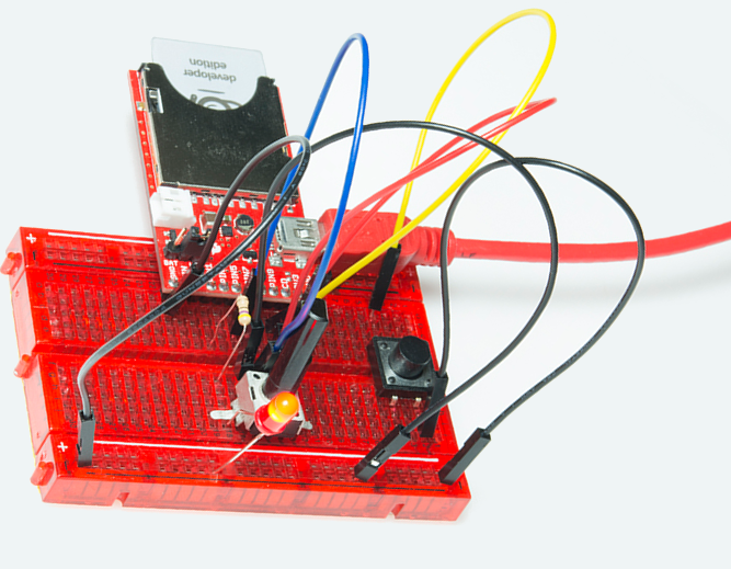
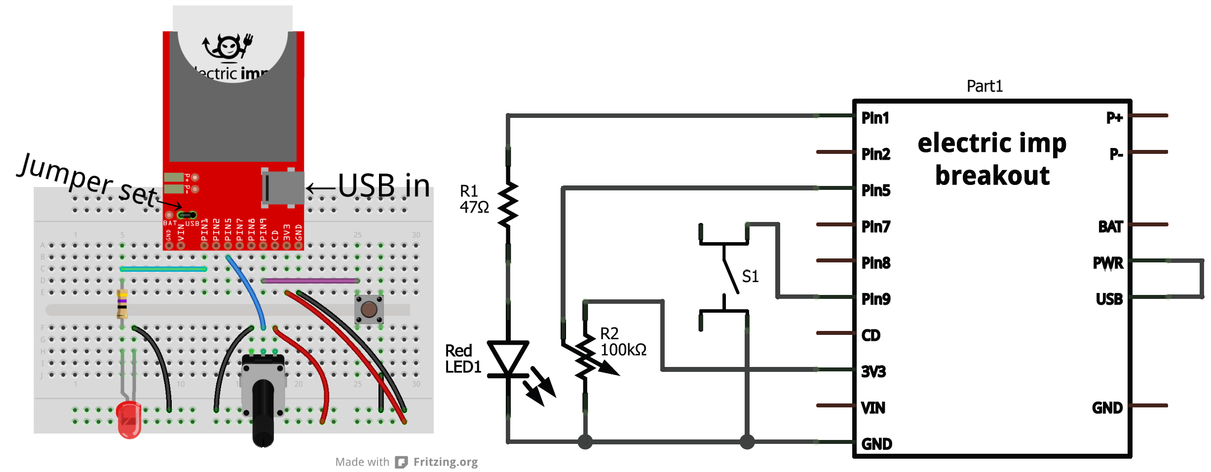
The setup for this example code requires three unique components: an LED, potentiometer, and a button (plus a current-limiting resistor for the LED). Here's a fritzing diagram and schematic (click to see it bigger) for our circuit:
Make sure the imp is getting power. USB is usually the quickest/easiest way to apply power to the breakout board, but you'll need to set the jumper accordingly.
The Code
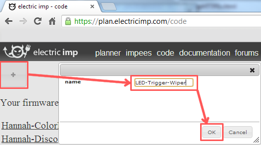
To create a new piece of code, click over to the "Code" tab of the planner. Then click the "+" in the top left and give your new piece of code a name (we'll go with "LED-Trigger-Wiper").
This'll open up a blank piece of code. Copy and paste everything from the below box, into your code window and save.
language:Squirrel
/* Digital Input, Analog Input, PWM Output Example
   by: Jim Lindblom
   SparkFun Electronics
   date: July 15, 2013
   license: Beerware. Use, reuse, and modify this code however you see fit.
   If you find it useful, buy me a beer some day!

   This is a simple piece of code which uses an LED, potentiometer, and button.
   The LED connects to pin 1 through a 47 ohm resistor. The cathode of the LED should connect to ground.
        This means writing pin 1 will turn the LED on, and writing it to 0 turns the LED off.
   The button connects on one side to pin 9, and the other pin of the button goes to ground.
        We'll use the internal pull-up resistors on pin 9 to bias the button high.
        When the button is pressed, pin 9 should read as low.
   The wiper of the potentiometer is connected to pin 5. The other two pins of the pot should be
        connected to +3.3V and GND. This'll make the voltage at pin 5 adjustable from 0-3.3V.
*/

////////////////////////////////////////
// Function definitions               //
////////////////////////////////////////

local ledState = 1; // Says local, but think of this as a global var. Start with LED on

// function pin9Changed() will be called whenever pin 9 goes from high->low or low->high
function pin9changed()
{
    local buttonState = hardware.pin9.read(); // Read from the button pin

    if (buttonState == 0) // Button will read low if pressed
    {
        ledState = ledState ? 0 : 1;    // Flip flop ledState
        server.log("Button pressed!");
    }
    else // Otherwise button was released, no action
    {
        server.log("Button released");
    }
}

// Loop constantly updates the LED. If ledState is 1, we'll read the pot, and set the LED brightness accordingly.
// If ledState is 0, we'll just turn the LED off. ledState is updated in the pin9Changed() function.
function loop()
{
    if (ledState == 1)
    {
        local rawValue = hardware.pin5.read();  // Read from the potentiometer. Returns a value between 0 and 65535.
        rawValue /= 65535.0;  // Make rawValue a % (and a float). The pin write function requires a value between 0 and 1.
        hardware.pin1.write(rawValue);  // Pin 1 is already configured as PWM, write potentiometer value
    }
    else
    {
        hardware.pin1.write(0);  // Write pin 1 low -- LED off
    }

    // This must be called at the end. This'll call loop() again in 10ms, that way it'll actually loop!
    imp.wakeup(0.01, loop);
}

////////////////////////////////////////
// Setup Stuff: Runs first at startup //
////////////////////////////////////////
hardware.pin1.configure(PWM_OUT, 0.0005, 0.0);   // Configure Pin 1 as PWM output, 5ms period, 0% high (off)
hardware.pin5.configure(ANALOG_IN); // Configure pin 5 as analog input
hardware.pin9.configure(DIGITAL_IN_PULLUP, pin9changed); // Configure pin 9 as digital input (with pull-up enabled). On change it'll call function pin9changed().
imp.configure("LED Trigger Wiper", [], []);

loop(); // Call loop, and let the program go!
This'll save a copy to your account on electric imp's server. You'll now always be able to open it up, view it, and modify it by clicking on the link in the "code" tab.
The code creates a simple adjustable-brightness LED controller. The brightness of the LED is adjusted by turning the potentiometer. Pressing the button will turn the LED on and off.
Explaining the Code
If you're only used to working with Arduino sketches, this code may make very little sense, electric imp programs have a very different "flow" to them. Begin by looking at the 5 lines of code at the bottom of the program (under the "Setup Stuff" header). This is actually where our imp starts when it begins to run it's code. Everything above is simply a function definition.
Most of this code makes heavy use of the imp's pin class, which handles a lot of the I/O control. If you're used to using Arduino GPIO's, the imp's API isn't too different. You have to set the pin up as either an input or output, analog or digital. Then write or read to the pin accordingly.
At the end of the setup, we make a call to the loop() function, which is defined above. loop() is simple, it checks a global variable named ledState. If ledState is 1, we read the potentiometer voltage, and adjust the brightness of our LED accordingly. The special sauce making loop actually loop is the last line of code in the function: imp.wakeup(0.01, loop). The imp.wakeup function puts the imp to sleep, but sets a timer. When the timer goes off, the loop() function is called from the beginning. In this case we set the timer to 0.01 seconds (10ms), so loop() should run about 100 times a second. This is really the only way to make the electric imp "loop" like an Arduino might.
The ledState variable is flip-flopped in the pin9changed() function. This is like an interrupt. It's called whenever the state of pin 9 changes -- if it goes from high to low, or low to high. When setting up pin 9 as a digital input, we added this function as the one to be called when the state change occurred.
Check out the comments in the code for a more in-depth overview of each function call. Or, for more information, check out electric imp's API reference.
The next example will make use of the imp's greatest feature...it's web connectivity.