RFM69HCW Hookup Guide
 MikeGrusin
Running the Example Code
Felix Rusu of LowPowerLab has written an excellent Arduino library for the RFM69 that handles the details of setting up the module and sending and receiving data. This guide will cover interfacing the RFM69HCW to an Arduino microcontroller using this library.
If you're using a different microcontroller, the information here plus the datasheet and the RFM69 library source code should help get you up and running. (If you write example code for another system, we'll be glad to add it to our code repository).
Note that the author of the library keeps the most up-to-date version at github.com/LowPowerLab/RFM69. SparkFun has created their own repository for the RFM69HCW Breakout Board that includes a copy of this library plus hardware schematics, example code, etc. at github.com/sparkfun/RFM69HCW_Breakout.
Installing the RFM69 Library
Hopefully you've done a bit of Arduino programming and know how to install a library. If not, take a look at our tutorials on the process:
- Installing the Arduino IDE
- Using Github (to retrieve the example code and library)
- Installing an Arduino Library
NOTE: This library is not found in the Arduino Library Manger currently, so you'll have to download the library and add it using the Add .ZIP Library... option found under the Sketch > Include Library menu.
The basic process is:
Download a copy of the repository:
RFM69HCW GitHub Repository Open the above archive, go into the "Libraries/Arduino" folder, copy the "RFM69" folder, and add the folder via the Library Manager or paste it into your "Arduino/libraries" folder.
Restart your Arduino IDE.
Easy!
Plug in the Hardware
In this tutorial we're going to set up two Arduino / RFM69 nodes and get them to communicate with each other.
If you haven't yet, do the wiring steps on the Hardware Connections page of this tutorial.
At this point, you should have two matching Arduino plus RFM69HCW nodes. We'll need to figure out the serial ports associated with these nodes. Plug one USB cable into your computer. A new COM port number should be added to the Arduino IDE's "Tools/Port" list. Write it down. Now plug in the other USB cable from the second node. Another COM port number should appear. Write that one down as well.
Customize the Code for Each Node
Before you upload the code to your Arduino, you'll need to customize it for each node. Use the code below, and make the followinf changes for each separate node.
Node 1
Let's set it up for your FIRST node:
Near the top of the code, look for
#define NETWORKID, and change the value to 0. This will be the network all your nodes are part of, so it should be the same for all your nodes. (You can of course make this any number from 0 to 255, as long as it's the same for all your nodes.)Now look for the
#define MYNODEIDline, and change the value to 1. That will be this node's address.Look for the
#define TONODEIDline, and change the value to 2. That will be the other node's address; the one you'll be talking to.Below these lines will be a section for defining the radio frequency of your RFM69HCW board. Uncomment the line corresponding to your board's frequency, and make sure the others are commented (have // in front of them. If you forget it, the frequency is marked on the bottom of your RFM69HCW board).
If you want to use encryption, change the
#define ENCRYPTvalue totrue, and put a 16-character string of your choice into theENCRYPTKEYvalue. This key must be the same for all nodes on your network. Keep it a secret!Finally, if you wish to use acknowledgements, set
USEACKtotrue. If not, set it tofalse. Use the same setting for all your nodes.
// radio.setCS(10); //uncomment this if using Pro Micro
Now upload the sketch to your FIRST node. Remember that you should set the "Tools/Port" menu to the COM port you wrote down earlier for the FIRST node, and if you're using a 3.3V Arduino Pro as we recommend, you should set the "Tools/Board" menu to "Arduino Pro or Pro Mini" and "Tools/Processor" to "ATmega328 (3.3V, 8MHz)"
Node 2
Time to modify the sketch for the SECOND node.
Go back up to the
#define MYNODEIDline, and change the number to 2. That will be this node's address.Now look for the
#define TONODEIDline, and change the number to 1. That will be the other node's address; the one you'll be talking to.
See how we swapped the MYNODEID and TONODEID numbers? This way each node will send messages to the other one.
Upload the sketch to your SECOND node. Change the "Tools/Port" menu to the second COM Port you wrote down from above, and upload. That's it, we're done!
Load and Modify the Code
Copy the code from the below window into the Arduino IDE (be sure the editing window is completely blank first). After you've installed the RFM69 library, you can also find this code in the Arduino IDE under "File / Examples / RFM69 / SFE_RFM69HCW_example.ino". Don't forget to make the changes mentioned above.
language:c
// RFM69HCW Example Sketch
// Send serial input characters from one RFM69 node to another
// Based on RFM69 library sample code by Felix Rusu
// http://LowPowerLab.com/contact
// Modified for RFM69HCW by Mike Grusin, 4/16

// This sketch will show you the basics of using an
// RFM69HCW radio module. SparkFun's part numbers are:
// 915MHz: https://www.sparkfun.com/products/12775
// 434MHz: https://www.sparkfun.com/products/12823

// See the hook-up guide for wiring instructions:
// https://learn.sparkfun.com/tutorials/rfm69hcw-hookup-guide

// Uses the RFM69 library by Felix Rusu, LowPowerLab.com
// Original library: https://www.github.com/lowpowerlab/rfm69
// SparkFun repository: https://github.com/sparkfun/RFM69HCW_Breakout

// Include the RFM69 and SPI libraries:

#include <RFM69.h>
#include <SPI.h>

// Addresses for this node. CHANGE THESE FOR EACH NODE!

#define NETWORKID     0   // Must be the same for all nodes
#define MYNODEID      1   // My node ID
#define TONODEID      2   // Destination node ID

// RFM69 frequency, uncomment the frequency of your module:

//#define FREQUENCY   RF69_433MHZ
#define FREQUENCY     RF69_915MHZ

// AES encryption (or not):

#define ENCRYPT       true // Set to "true" to use encryption
#define ENCRYPTKEY    "TOPSECRETPASSWRD" // Use the same 16-byte key on all nodes

// Use ACKnowledge when sending messages (or not):

#define USEACK        true // Request ACKs or not

// Packet sent/received indicator LED (optional):

#define LED           9 // LED positive pin
#define GND           8 // LED ground pin

// Create a library object for our RFM69HCW module:

RFM69 radio;

void setup()
{
  // Open a serial port so we can send keystrokes to the module:

  Serial.begin(9600);
  Serial.print("Node ");
  Serial.print(MYNODEID,DEC);
  Serial.println(" ready");

  // Set up the indicator LED (optional):

  pinMode(LED,OUTPUT);
  digitalWrite(LED,LOW);
  pinMode(GND,OUTPUT);
  digitalWrite(GND,LOW);

  // Initialize the RFM69HCW:
  // radio.setCS(10);  //uncomment this if using Pro Micro
  radio.initialize(FREQUENCY, MYNODEID, NETWORKID);
  radio.setHighPower(); // Always use this for RFM69HCW

  // Turn on encryption if desired:

  if (ENCRYPT)
    radio.encrypt(ENCRYPTKEY);
}

void loop()
{
  // Set up a "buffer" for characters that we'll send:

  static char sendbuffer[62];
  static int sendlength = 0;

  // SENDING

  // In this section, we'll gather serial characters and
  // send them to the other node if we (1) get a carriage return,
  // or (2) the buffer is full (61 characters).

  // If there is any serial input, add it to the buffer:

  if (Serial.available() > 0)
  {
    char input = Serial.read();

    if (input != '\r') // not a carriage return
    {
      sendbuffer[sendlength] = input;
      sendlength++;
    }

    // If the input is a carriage return, or the buffer is full:

    if ((input == '\r') || (sendlength == 61)) // CR or buffer full
    {
      // Send the packet!


      Serial.print("sending to node ");
      Serial.print(TONODEID, DEC);
      Serial.print(", message [");
      for (byte i = 0; i < sendlength; i++)
        Serial.print(sendbuffer[i]);
      Serial.println("]");

      // There are two ways to send packets. If you want
      // acknowledgements, use sendWithRetry():

      if (USEACK)
      {
        if (radio.sendWithRetry(TONODEID, sendbuffer, sendlength))
          Serial.println("ACK received!");
        else
          Serial.println("no ACK received");
      }

      // If you don't need acknowledgements, just use send():

      else // don't use ACK
      {
        radio.send(TONODEID, sendbuffer, sendlength);
      }

      sendlength = 0; // reset the packet
      Blink(LED,10);
    }
  }

  // RECEIVING

  // In this section, we'll check with the RFM69HCW to see
  // if it has received any packets:

  if (radio.receiveDone()) // Got one!
  {
    // Print out the information:

    Serial.print("received from node ");
    Serial.print(radio.SENDERID, DEC);
    Serial.print(", message [");

    // The actual message is contained in the DATA array,
    // and is DATALEN bytes in size:

    for (byte i = 0; i < radio.DATALEN; i++)
      Serial.print((char)radio.DATA[i]);

    // RSSI is the "Receive Signal Strength Indicator",
    // smaller numbers mean higher power.

    Serial.print("], RSSI ");
    Serial.println(radio.RSSI);

    // Send an ACK if requested.
    // (You don't need this code if you're not using ACKs.)

    if (radio.ACKRequested())
    {
      radio.sendACK();
      Serial.println("ACK sent");
    }
    Blink(LED,10);
  }
}

void Blink(byte PIN, int DELAY_MS)
// Blink an LED for a given number of ms
{
  digitalWrite(PIN,HIGH);
  delay(DELAY_MS);
  digitalWrite(PIN,LOW);
}
Running the Sketches
You now have two nodes that will send messages to each other, but, to use them, we'll need to open two serial terminals.
One way to do this is to run two separate Arduino IDEs. You'll have to actually start Arduino twice - you can't just open a "new" code window from the first IDE.
Set one IDE to the COM port of the first node and the other to the COM port of the second. Then, open serial monitor windows from both IDEs.
In each serial monitor window, you'll need to set the baud rate to 9600 and make sure the "line ending" dropdown is set to "carriage return." (The example code uses carriage returns as a signal to send a packet.)
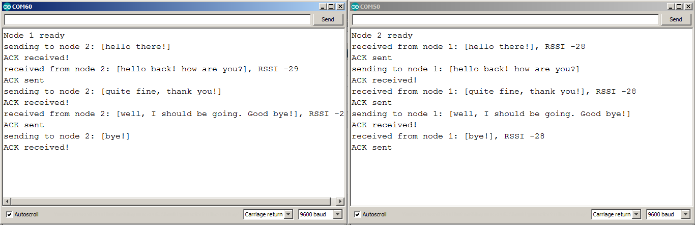
Once both windows are up, you should be able to type messages in the text entry box at the top of one window and press return to send the message to the other window. Try it!
You can also try turning ACKs and encryption on or off, using the "broadcast address" (255), etc.
You can also try this one of the many serial terminals mentioned in this tutorial.
Signal Strength
You might have noticed the "RSSI" number that the example code prints out. "RSSI" stands for "Receive Signal Strength Indicator;" it's a measurement of how strong the transmission was when a message was received.
This number is in decibels (dB), which means that when nodes are close to each other this will be a low number like -25, and, when they're further away, they'll be higher numbers like -50. Usually you'll ignore this number, but you could use it to estimate how far away nodes are from each other, provide a warning when the link is becoming weak, or, in sophisticated applications, vary the transmit strength so that you don't waste power unnecessarily.
Note: In this section and the example code, the notation of "number(s)" is in reference to the value's magnitude, as the signal strength is usually reported in values less than 0. To be technically accurate, the lower the value, the lower the power of the signal strength. (i.e. The value (-50)dB is less than (-25)dB; therefore, (-50)dB has a weaker signal strength and is probably further away.)