RGB Panel Hookup Guide
 jimblom
Powering the Panel
Power Connector
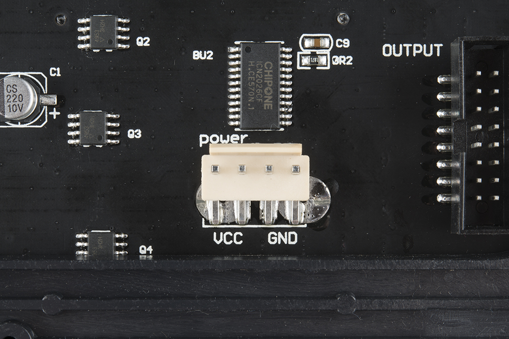
These panels require a regulated 3.3-5V supply for power. And that supply needs to be able to source a good amount of current -- up to 2A in the worst case (all pixels bright, hot, white). For a 32x64, one of these panels was pulling about ~3.36A-3.43A without a heat sink -- so about up to 4A worst case. A 4-pin (2 for VCC, 2 for GND), 0.15"-pitch polarized connector should be used to supply power to the panel. Depending on the manufacturer, the color and location of the power connector may be different.
Power Cable
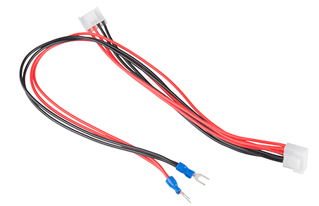
Included with the panel is a dedicated cable for power. It's a 0.15" pitch 4-pin polarized connector. The included cable is terminated with both a female polarized connector, and a pair of spade terminals.
Here are a few methods we've used to power the panel. If you are powering the Arduino with a different voltage, make sure to connect GND in order to have the same reference voltage.
Longer-Term: 12V/5V Power Supply Breakout Board
This is our recommended combo:
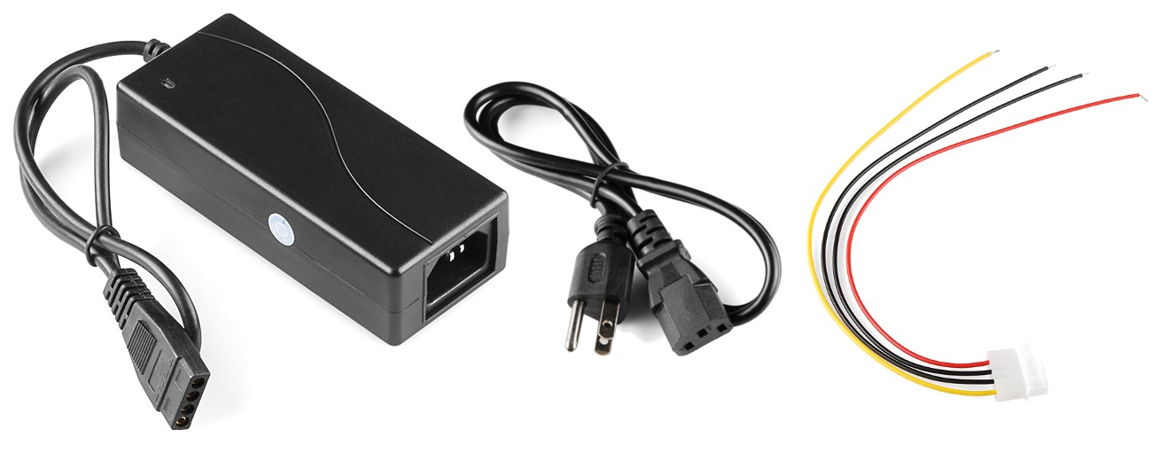
- A 12V/5V 2A Power Supply, which should be enough to keep the display running. (Just don't hook up the 12V output to it!). Note: If you are using an older 12V/5V power supply, you will need the three prong IEC C13 Cable to connect AC power to the supply.
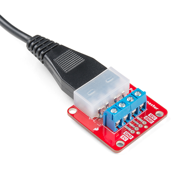
- Breakout Board with Molex connector and 5mm screw terminals soldered. Note: The spade connector for the panel's GND pin can be connected to both GND pins of the screw terminal. Just make sure to not connect it to the 12V or 5V side.
- Strip two pieces of wire and connect a male DC barrel jack adapter with a screwdriver to an Arduino's barrel jack for VIN. Note: Most Arduinos should have a voltage regulator that can handle the input between 7-12V, just make sure to check out the specs on the development board before powering up.
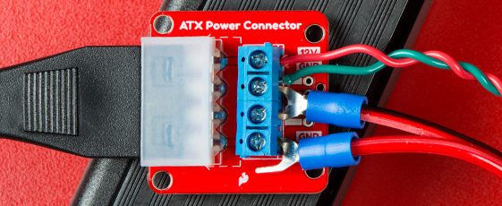
Your final connection should look similar to the closeup of the connection below with the LED panel's forked spade connector and wires inserted into the screw terminals.
Longer-Term: 12V/5V Power Supply Splicing Wires
You can also splice the wires using the following combinations:
- A 12V/5V 2A Power Supply, which should be enough to keep the display running. (Just don't hook up the 12V output to it!). Note: If you are using an older 12/5V power supply, you will need the three prong IEC C13 Cable to connect AC power to the supply.
- A 4-pin Molex Connector w/ Pigtail to interface the supply to panel.
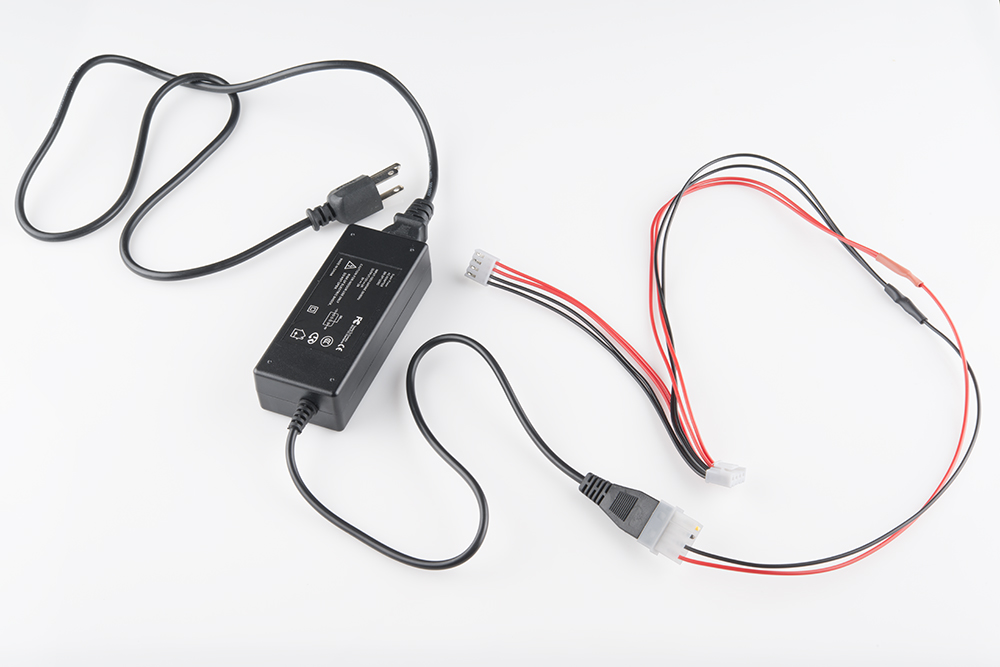
To begin, we snipped the spade connectors off of the panel power supply cable. And then stripped the newly unterminated ends.
Then we spliced the Molex pigtail to the LED panel's power cable by connecting the red wires together. Do the same for the black wires (make sure you use the black wire next to the red on the Molex pigtail). Make sure you are connecting to the 5V and GND pins and NOT the 12V pin. Before connecting to the RGB Matrix Panel, test the connection with a multimeter.
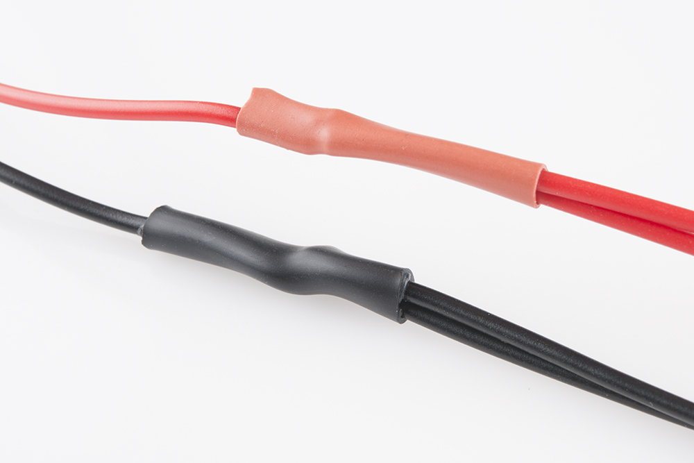
Finally, cover the splice with heat shrink or electrical tape, and voila! That's a beautiful power cable.
This is a nice, sturdy interface between the panel and a solid power supply. If you're looking for something easier, but less reliable check the below option.
Long-Term: Mean Well Switching Power Supply
For those that want to push the panels to the limit (i.e. setting the pixels on a 32x64 panel at full white at maximum capacity), combine:
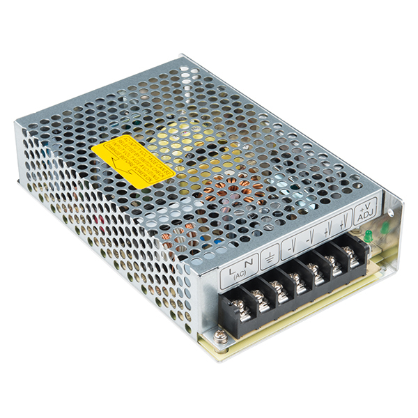
- A 5VDC/20A Mean Well switching power supply - which is more than enough for your panel.
- A wall adapter cable (North America or European standard) depending on your country.
Short-Term: Barrel Jack
Grab a 5V wall adapter. Both been tested to work with the panels as well. At least in the short term.
Use the power supply in conjunction with a female barrel jack adapter and screwdriver to get a quick and dirty connection between the spade and barrel jack.
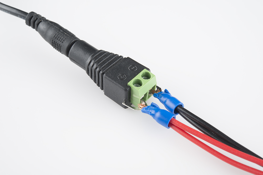
The final connection should look like the image below.
