RN-52 Bluetooth Hookup Guide
 Joel_E_B
Hardware Setup
Before you can configure the module, some hardware needs to be connected. This section will cover the necessary hardware needed to work with the RN-52.
Materials Needed
Aside from an RN-52 Breakout, you will need the following:
Wiring the RN-52
In order to use the RN-52, you must first decide how you will connect external hardware to the breakout board. One option is to solder female headers to both sides of the breakout. Second, you can solder wire directly to the breakout. Another option, and the one that will be used in all the demos in this tutorial, is to solder straight male headers to the breakout so that it can be used in a breadboard.
*Note: The RN-52 breakout is too large to fit on a standard breadboard. Thus, you will need to attach two breadboards side by side.
*Note: The antenna on the RN-52 is very sensitive to interference. When placing the breakout on a breadboard, be sure that the antenna is hanging off the breadboard as far as is will go. This will prevent the metal inside the breadboard from interfering with the range of the module. Keep this in mind if you are designing your own PCB as well.
Power
First and foremost, the RN-52 is a 3.3V device. It can handle an input voltage of about 3.0 - 3.6V. Voltages above or below this range can result in the module not working properly or, worse, damaging the module. Make sure you select a power supply that can provide the correct amount of voltage to the device.
In this example, we'll be using an Breadboard Power Supply to provide 3.3V to the breakout. If you would like to power the breakout with a battery, make sure the battery can provide the correct amount of voltage. We recommend using a LiPo Battery in conjunction with the LiPower board set for 3.3V.
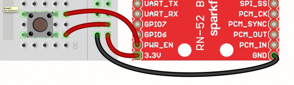
As usual, connect the GND pin to GND, and connect the 3.3V pin to the Vcc pin on the supply. That just leaves the power enable pin (PWR_EN). This can be hooked up one of two ways. The first method is to simply jumper the PWR_EN pin to 3.3V. This will cause the module to start up immediately once it is powered.

The PWR_EN pin can also be attached to a button to allow the user to power up the module when it is desired, even if power is already supplied. This is useful in headset/hands-free applications where a battery is attached to the module but the module doesn't need to be on all the time.
GPIO9
GPIO9 is used to tell the module to enter command mode. If GPIO9 is HIGH or left floating, the module will remain in its default data mode, streaming audio or data. In order to enter command mode, GPIO9 must be pulled LOW. This can be accomplished by simply connecting GPIO9 to GND with a jumper wire. In this example, a switch is used to easily enter and exit command mode.
UART
You will need a way to communicate to the module and send commands. This will be accomplished with a 3.3V FTDI Basic. Connect GND to GND, TXO to UART_RX, and RXI to UART_TX. Those are the only connections needed to talk to the module.
With that, you should have something that looks like this:
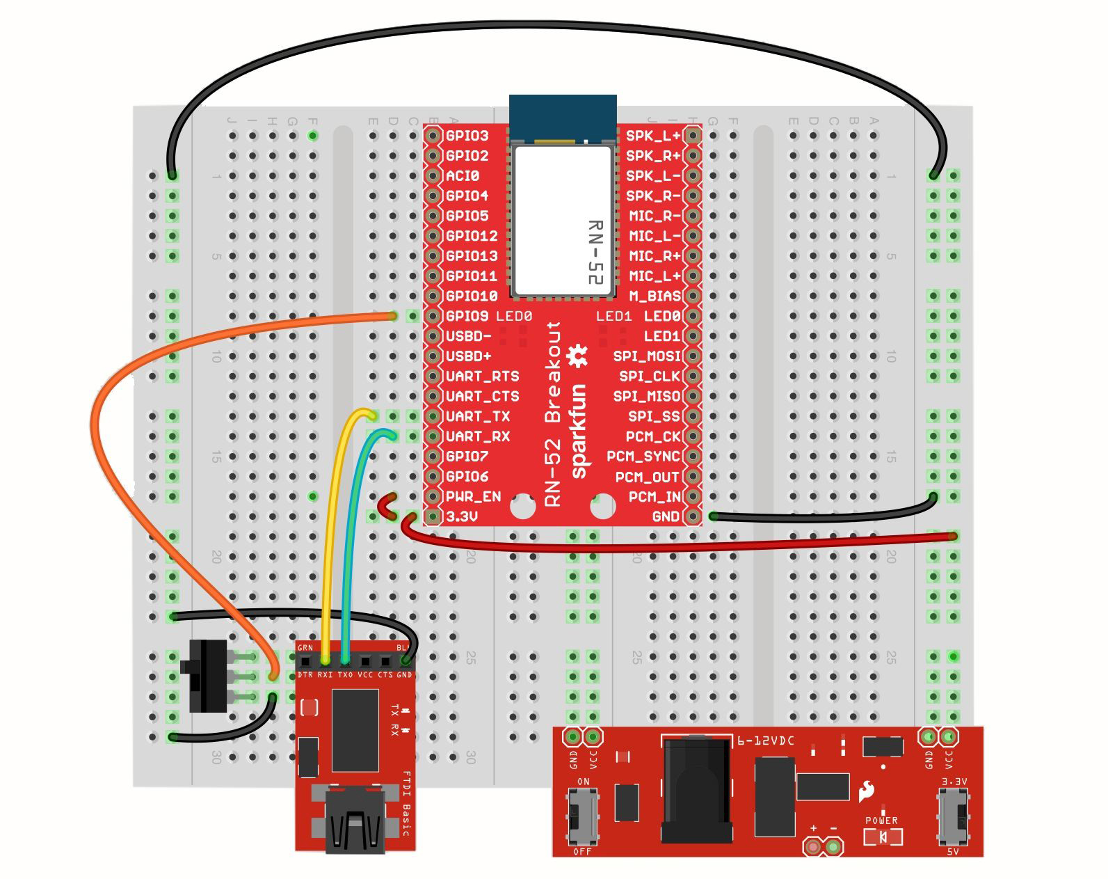
We're now ready to dive in and see how the RN-52 can be configured.