Rotary Switch Potentiometer Hookup Guide
 Byron J.
Project I: 10 Item Selector
The first project we'll build is based off a comment we received on the Decade Resistance Kit. The idea was posed to build a selector that allows for the selection of ten distinct steps. It's probably not the best application for the decade box, but a great example for the Rotary Switch Potentiometer board.
We'll connect the board as a voltage divider between Vcc and ground, and add resistors to produce ten even steps. Ten even steps means nine of the same value resistor.
We don't want the divider to consume too much current, so we want the overall series resistance to be reasonably high. Using 10KΩ resistors gives us 90KΩ total. It will draw a modest 55 µA from 5V.
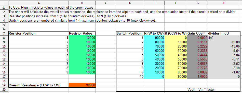
At 5V, this results in 0.555V per click of the switch, or about 113 ADC counts.
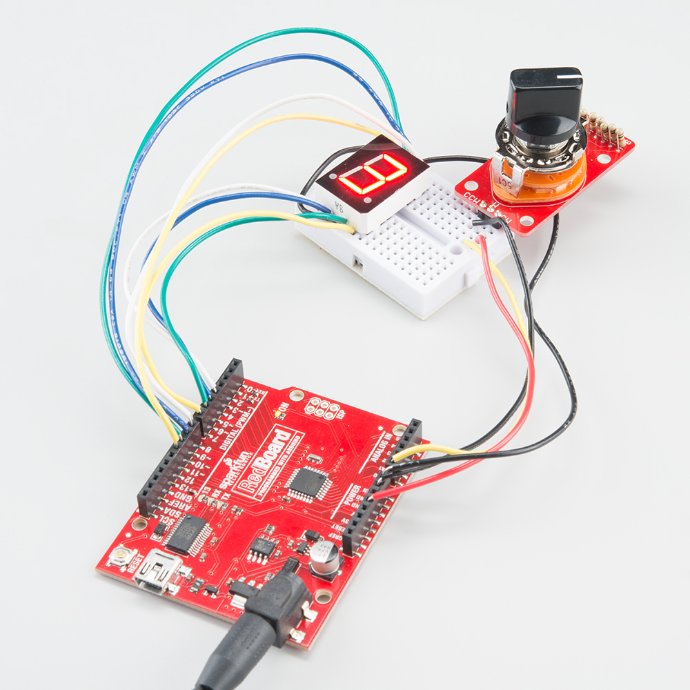
The switch was then wired as a voltage divider, and connected to ADC 0 on a RedBoard. We added a red 7-segment display on some unused port pins to show the switch setting. A description of the connections is in the sample sketch, below.
The code is fairly simple.
- It reads the ADC input.
- It does some math to translate the ADC value into the 0 to 9 range.
- It draws the step number by turning on the proper LEDs in the 7-segment display.
Here is the sample sketch.
language:c
/******************************************************************************
one_of_ten.ino
Rotary Switch Potentiometer Example
By Byron Jacquot @ SparkFun Electronics
April 21, 2015
https://github.com/sparkfun/Rotary_Switch_Potentiometer
Demonstrates using the Rotary Switch Potentiometer breakout board
with a microcontroller, to build a 10 position selector switch.
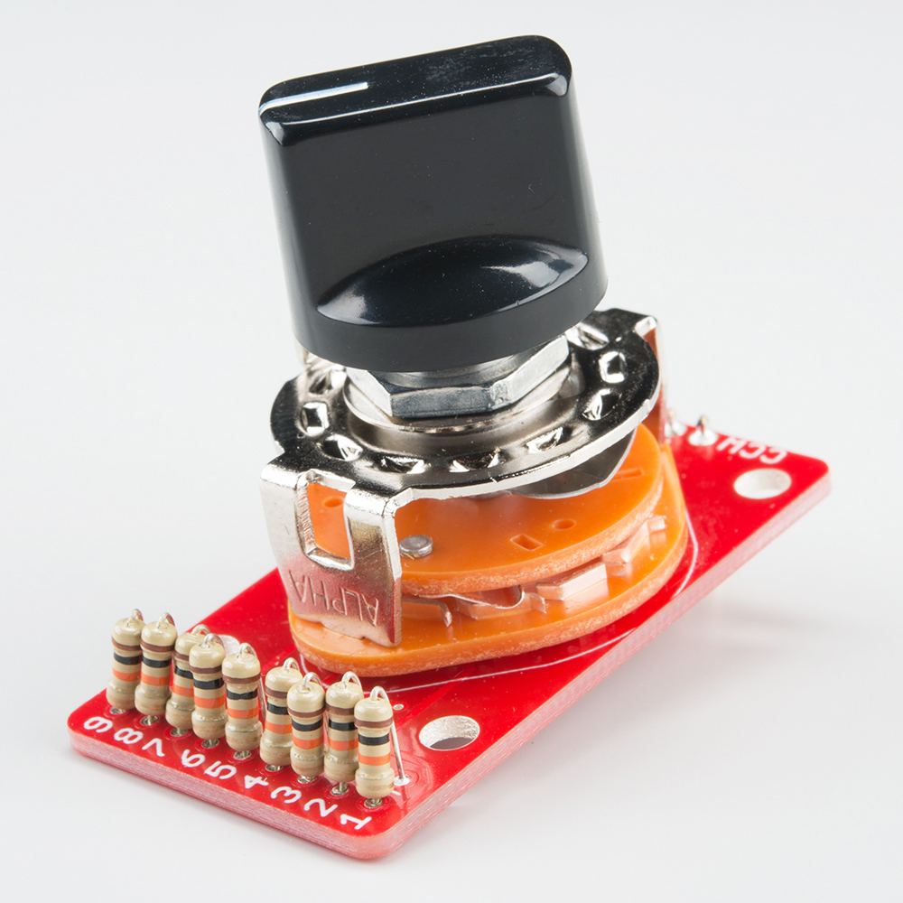
The Rotary Switch Potentiometer is a breakout board that adds 9 resistors to a
10 position rotary switch, to make a custom-taper, stepped potentiometer. This
example uses 9 10KOhm resistors, and connects the rotary switch potentiometer
to an analog input. The input is periodically scanned, and the current step
number is displayed on a 7-segment LED.
Development environment specifics:
This was developed using Arduino IDE 1.6.1
Using an Uno-compatible SparkFun RedBoard with a rotary switch potentiometer and
a 7-segment LED.
This code is beerware; if you see me (or any other SparkFun employee) at the
local, and you've found our code helpful, please buy us a round!
Distributed as-is; no warranty is given.
******************************************************************************/
/******************************************************************************
Hardware connections
--------------------
The test configuration was wired as follows:
The Rotary Switch Potentiometer board was populated with 10K resistors in
every position. It was connected to the RedBoard as follows:
RedBoard pin : Rotary Switch Potentiometer Pin
----------------------------------------------
GND : CCW
A0 : W
5V : CW
GPIO pins on the RedBoard drove the 7-segment display. See the 7-segment
display datasheet for the pin number assignment
(https://cdn.sparkfun.com/datasheets/Components/LED/YSD-160AR4B-8.pdf)
RedBoard pin : Rotary Switch Potentiometer Pin
----------------------------------------------
GND : 3, 8 LED Anodes
4 : 1, segment E
5 : 2, segment D
6 : 4, segment C
7 : 5, decimal point
8 : 6, segment B
9 : 7, segment A
10 : 9, segment F
11 : 10, segment G
******************************************************************************/
// Bitmaps for display digits 0 through 9.
// Pin ordering corresponds to the connections described in the table above.
// This data is treated as active high - we'll invert it
// when it's applied to the GPIO pins for the common-anode display
static const uint8_t font[10] = {0x77, 0x14, 0xb3, 0xb6, 0xd4, 0xe6, 0xe7, 0x34, 0xf7, 0xf4 };
// void drawLED(uint8_t val)
// Takes an input value and renders it on the 7-segment diaplay
// by driving each pin to the appropriate logic level for the character,
// as stored in the table above.
//
// It accepts a uint8_t as input, and truncates it to the 0-9 range.
void drawLED(uint8_t val)
{
uint8_t idx = val % 10; // truncate input to 0 to 9 range.
uint8_t mask = 0x01;
for(uint8_t pin = 4; pin <= 11; pin++)
{
// Starting at output pin 4, step through to pin 11.
// For each pin, check whether the corresponding bit in the font array
// is set, and if so, illuminate that LED.
//
// LED has inverse response - logic low turns it ON.
// So if a bit in the font is high, set that pin low
if(font[idx] & mask)
{
digitalWrite(pin, LOW);
}
else
{
digitalWrite(pin, HIGH);
}
mask <<= 1;
}
}
void setup() {
// put your setup code here, to run once:
Serial.begin(9600);
// initialize pins 4 through 11 as outputs.
pinMode(4, OUTPUT);
pinMode(5, OUTPUT);
pinMode(6, OUTPUT);
pinMode(7, OUTPUT);
pinMode(8, OUTPUT);
pinMode(9, OUTPUT);
pinMode(10, OUTPUT);
pinMode(11, OUTPUT);
}
void loop()
{
// put your main code here, to run repeatedly:
uint16_t input;
uint16_t val;
// read the ADC
input = analogRead(0);
// Translate ADC value from 0-1023 to 0-9.
// This implements the proportion
// input/1023 = val/9.
// One "step" of the pot is about 113 ADC counts.
// We're adding 65 (1/2 of 113) to the input value, so that the
// input is in the middle of the window, rather than right at the edge, so values
// are stable and solid.
val = (input+56)*9/1023;
// Take the calculated value and display it.
drawLED(val);
}
To expand on this example, we could add several more switches and displays, to build a sort of digital decade box -- a switch for the ones digit, a switch for the tens digit, and so on.