Rotary Switch Potentiometer Hookup Guide
 Byron J.
Project II: Analog Amplitude Control
The Rotary Switch Potentiometer is also useful in a variety of amplitude control situations.
In many disciplines where amplitude is important, it is often expressed in decibels (known as dB for short). We're not going to get too deep into the particulars here - the Wikipedia Article is much more detailed and complete.
There are a couple of things to keep in mind when describing things in terms of decibels.
The first thing is that decibels behave logarithmically, reducing large changes to regular changes in the decibel scale. In acoustics, if a sound doubles in pressure, it increases by 6 dB SPL. Each time it doubles, that's 6 additional dB. Because our auditory systems have extremely wide dynamic range, we can perceive sounds over a pressure range of greater than 1,000,000:1, or 100 dB SPL.
Also, the term "decibel" by itself simply describes the relative amplitude of two signals -- decibels are used in many different disciplines, such as acoustics, optics, and radio transmission. To recognize these differences, different suffixes are added. dB-SPL describes the amplitude of sound, while dBZ is used to describe the reflected signal in weather radar. A more complete list of different dB measurements can be found at Wikipedia. In order to communicate accurately, be sure to use the appropriate suffix.
If you don't firmly grasp decibels right here, keep reading, as they'll become more obvious as we explore the following examples.
Decibel Attenuation
The first amplitude control circuit that we'll build with the Rotary Switch Potentiometer is a resistor divider, with steps that are graduated to about 6 dB per click of the switch. A voltage divider that is configured to reduce signal amplitude by a particular amount is also known as an attenuator.
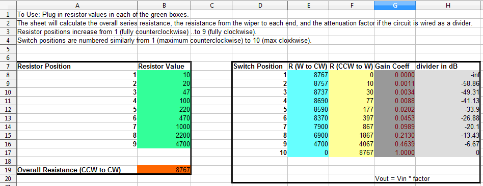
Playing with the values from the Resistor Pack, we find that we get roughly 6 dB attenuation per step if each resistor is about double the value of it's predecessor. Picking only values in the kit, we find a reasonable fit in a series of resistors of 10, 22 and 47 Ohms, then 100, 220, and 470, and so on.
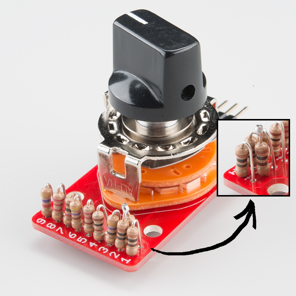
You'll notice that the attenuation per step (the light gray column) isn't exactly 6 dB, but it is pretty close. By limiting ourselves to the resistors in the kit, we only have a few values to pick from. You may have also noticed that the kit is lacking a 22Ω resistor -- as a substitute, we've installed two 10Ω resistors in series (shown in the photo inset). If you want to make a more precise attenuator, you can switch to 1% (or even 0.1%) tolerance resistors, which come in many more values.
Decibel Gain
The reverse of an attenuator is a variable gain amplifier. Where dividers and attenuators can only reduce the voltage, by adding an amplifier, we can also increase the voltage.
The SparkFun Sound Detector is a small board with a microphone, an amplifier stage, and some signal conditioning to indicate the presence of sound. The board can be made more or less sensitive by installing a resistor to change the gain of the amplifier stage. There are tables of suggested fixed resistor values illustrated in the Sound Detector Hookup guide.
While we could install a regular linear-taper pot for the calibration resistor, we'd find that most of the change was bunched up at one end of the rotation. The rest of the travel would have only a tiny effect. Alternately, we could install an audio-taper pot in reverse. The change would be more obvious, but turning the pot up (clockwise) would make the circuit less sensitive -- somewhat counterintuitive. There are "reverse audio" taper pots, but they can be hard to find. Instead, we'll use the Rotary Switch Potentiometer board to build a gain control.
If you take a close look at the tables in the sound detector hookup guide, you'll notice that with R3 installed we can only reduce the gain. For gain that can go both up and down, we'll remove R3. From there, let's look at resistor values that make the sound detector configurable over a significant range. As with the attenuator described above, let's shoot for about 6 dB per step.
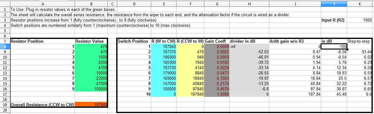
This sheet adds some new columns that calculate the behavior of the sound detector, including the arithmetic gain, gain in dB, and the relative change from step-to-step. Looking at that step-to-step gain column, you'll notice that the first step is very large, because the furthest counterclockwise setting has a gain of zero, effectively turning the amplifier off.
At the 9th position, the gain is 38.87 dB, very close to the 40 dB of the plain Sound Detector - we have added one step above, and eight below.
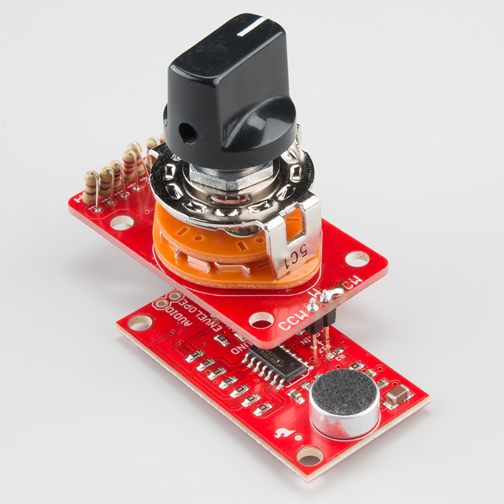
As mentioned in our description of variable resistors, you'll notice that the wiper (W) and clockwise (CW) pins have been joined with a solder blob. The CCW and W pins are installed in the R17 space via a 2-pin header, and R3 was removed entirely.
The combination behaves as we would expect - turning down the knob reduces the sensitivity, so that the detector doesn't trigger on quieter sounds. Turning the knob all the way up makes the detector so sensitive that the air conditioning background noise at the author's workbench triggers the detector intermittently.