SAMD51 Thing Plus Hookup Guide
 Englandsaurus
 Introduction
SparkFun is proud to welcome the SAMD51 Thing Plus to our microcontroller lineup! With a 32-bit ARM Cortex-M4F MCU, it is one of our most powerful microcontroller boards yet.
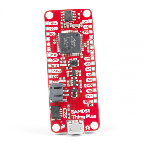
The ATSAMD51J20 microcontroller boasts a maximum CPU speed of 120MHz, 1MB of flash memory, 256KB of SRAM, up to 6 SERCOM interfaces, amongst other features (see datasheet). The SAMD51 Thing Plus provides a USB interface for programming and power, a Qwiic connector, 600mA 3.3V regulator, and LiPo charger all in a feather pin layout. For a full list of details, check out the Hardware Overview section below. In addition, this board comes flashed with the same convenient, UF2 bootloader as the RedBoard Turbo.
This tutorial aims to familiarize you with the new SAMD51 Thing Plus and help you get started using it. If you are new to the world of Arduino or microcontrollers, please check out our RedBoard Qwiic and RedBoard Qwiic Hookup Guide.
Required Materials
To get started, all you need is a few things:
- SAMD51 Thing Plus - You'll definitely need this; otherwise, you are probably on the wrong tutorial page (wink).
- USB micro-B Cable - 6 Foot - The USB interface serves two purposes: it powers the board and allows you to upload programs to it. (You might even have a few of these in you drawer!)
- Computer with the Arduino IDE installed on it - That is how we will program the board and interface with it.
That is ALL... pretty simple right? Now you won't be able to do much since there are no additional sensors to interact with the physical world. However, you can at least blink an LED and do some math calculations.
Jumper Modification Headers & Accessories ARM Programmers
wish to perform. Feel free to modify the items in your cart to fit your needs.
Jumper Modification
If you would like to modify the 3.3V/5V I/O jumper or A4/A5 Qwiic connector jumpers, you will need soldering equipment and/or a knife.


Qwiic Example
If you would like to follow along with the examples below to interact with the physical world, you will also need the following items:

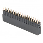
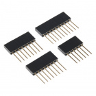
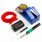
Headers & Accessories
If you would like to add headers to your board, check out some of the following items:


Below is a sample selection of our other headers and soldering tools in our catalog. For a full selection of our available Headers or Soldering Tools, click on the associated link.

ARM Programmers
If you would like to debug or flash your ARM processor on your own, here are some of our ARM Programmers:
Suggested Reading
Before continuing on with this tutorial, you may want to familiarize yourself with some of these topics if they’re unfamiliar to you:
Installing an Arduino Library
What is an Arduino?
Installing Arduino IDE
Adding More SERCOM Ports for SAMD Boards
How to Solder: Through-Hole Soldering
One of the new, advanced features of the board is that it takes advantage of the Qwiic connect system. We recommend familiarizing yourself with the Logic Levels and I2C tutorials (above) before using it, as all Qwiic sensors utilize an I2C communication protocol. Click on the banner above to learn more about Qwiic products.
UF2 Bootloader & Drivers
The SAMD51 Thing Plus is now easier than ever to program, thanks the UF2 bootloader. With the UF2 bootloader, the SAMD51 Thing Plus shows up on your computer as a USB storage device without having to install drivers for Windows 10, Mac, and Linux!
From the Arduino IDE, you'll still need to select the correct port on your machine, but you can just as easily use another programming language such as CircuitPython or MakeCode, which will be available in the near future.
Windows 7
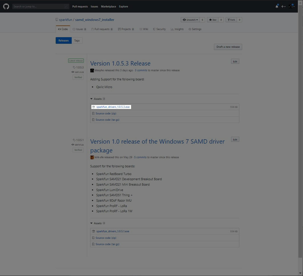
If you are using a Windows 7 OS, you will need to install the SAMD drivers using the SAMD Windows 7 Installer. Head over to the GitHub repo to install the executable.
Scroll down the page to the assets in the Latest release and click on the '.exe to download. The version number may be different depending on the release. The image below shows sparkfun_drivers_1.0.5.3.exe .
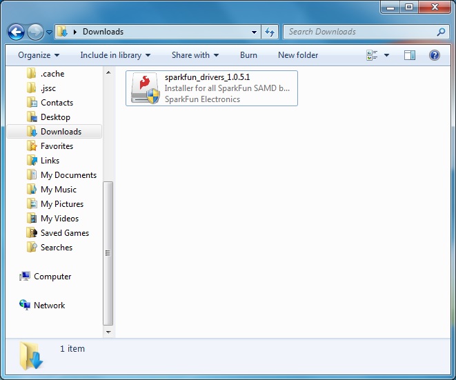
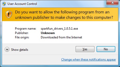
After downloading, click on the executable and follow the prompts to install. The steps to install are the same even though the following images show drivers for v1.0.5.1.
You will receive a warning from Windows. Click yes to continue.
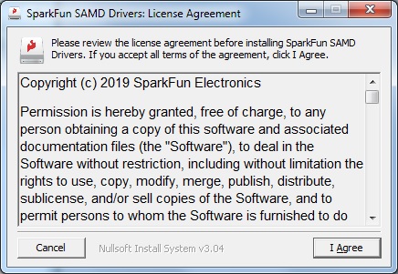
Another window will pop up. Read through the license and click "I Agree".
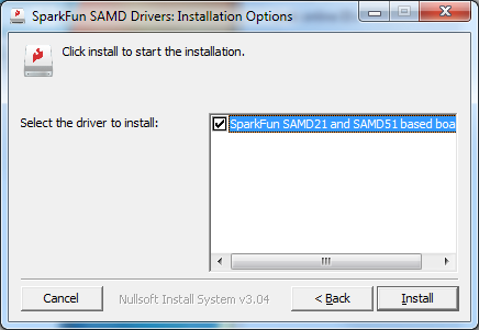
When ready, hit the Install button.
Another window will pop up. Click on "Install this driver software anyway" to continue.
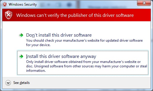
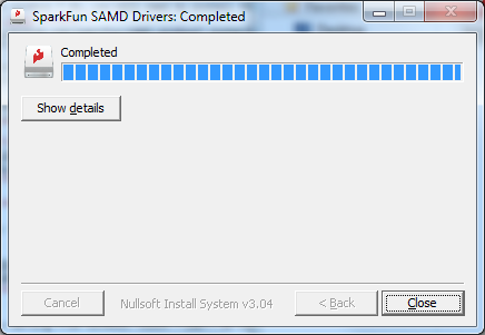
Your Windows 7 will begin installing the driver. This should take a few seconds. When the drivers have installed, hit the "Close" button to exit out of the installer.
What is UF2?
UF2 stands for USB Flashing Format, which was developed by Microsoft for PXT (now known as MakeCode) for flashing microcontrollers over the Mass Storage Class (MSC), just like a removable flash drive. The file format is unique, so unfortunately, you cannot simply drag and drop a compiled binary or hex file onto the SAMD51 Thing Plus. Instead, the format of the file has extra information to tell the processor where the data goes, in addition to the data itself.
For Arduino users, the UF2 bootloader is BOSSA compatible, which the Arduino IDE expects on ATSAMD boards. For more information about UF2, you can read more from the MakeCode blog, as well as the UF2 file format specifiation.
Double-Tap to Launch the Bootloader
The bootloader is what allows us to load code over a simple USB interface. To upload code, you will need to manually enter bootloader mode by rapidly double-tapping the reset button (after hitting the reset button once, you have about half a second to hit it again). The board will remain in bootloader mode until power cycles (happens automatically after uploading code) or the reset button is hit again (once).
On the SAMD51 Thing Plus, the there are a clues to if it is in bootloader mode:
- The D13 LED indicator will be a solid blue (may appear to be slowly fading or blinking).
- Board will show up under a different COM port.
- The board will appear as a USB mass storage device under the name 51THINGBOOT.
Driver Verification
To verify that your driver is working, you should see the difference in the following pictures after plugging in your SparkFun SAMD51 Thing Plus. Alternatively, once you have the Arduino IDE installed, you should also see a change in the number of available Serial/COM Ports (you may need to restart the Arduino IDE for the board to populate).
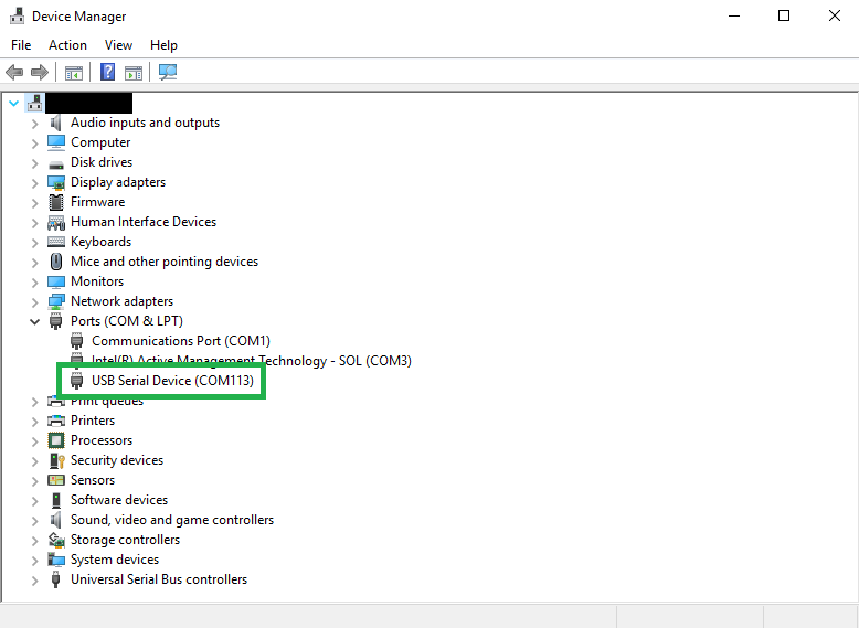
Windows
Check that the board shows up in your device manager. You can click the Start or ⊞ (Windows) button and type "device" to quickly search for the application. (*On Windows 10, the quick search function is picky on the spelling of the application you are searching for. For example, you may get results using "devi" and none for "device".)
Mac OSX
Open the Terminal and run the following command ls /dev/cu.* in the Terminal and check for the following changes (your board may show up under a different device name). To open the Terminal, open your Applications folder, Utilities folder, then double-click on Terminal. Otherwise, press ⌘ (Command) + space bar (Space Bar) to launch Spotlight and type "Terminal," then double-click the search result.
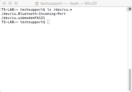
ls /dev/cu.*
Raspbian
Run the following command ls /dev/ttyACM* in the CLI/Terminal and check for the following changes (your board may show up under a different device name).
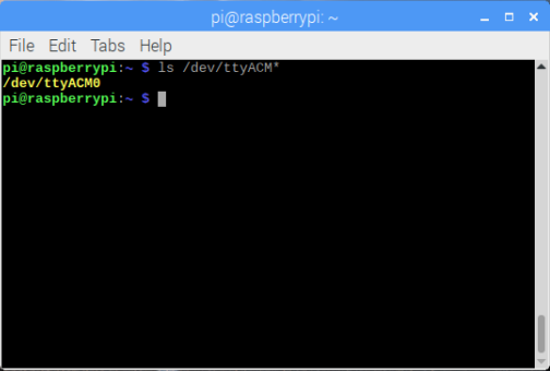
ls /dev/ttyACM*
Setting Up the Arduino IDE
Download/Install Arduino
You can download the Arduino IDE from their website. They have installation instructions, but we will also go over the installation process as well. Make sure you download the version that matches your operating system.
The installation procedure is fairly straightforward, but it does vary by OS. Here are some tips to help you along. We've also written a separate Installing Arduino tutorial in case you get stuck.
- We recommend using a computer with a full desktop operating system like Windows 10 (avoid Windows 7/8 due to driver issues), Mac OSX, and certain flavors Linux (check the Arduino FAQ page for compatibility).
- We do NOT recommend using a Chromebook, Netbook, tablet, phone, or the Arduino Web IDE in general. You will be responsible for troubleshooting any driver or Arduino Web IDE issues.
- As of writing this tutorial (05-21-2019), the most recent and stable release of the Arduino IDE is version 1.8.5. We recommend using that version of the Arduino IDE; you can download the previous releases here.
- On Windows 10, we do NOT recommend installing the Arduino IDE from the app store. You may run into issues because the OS will automatically update to the most recent release of the Arduino IDE, which may have unknown bugs (like the compiler errors in versions 1.8.6 and 1.8.7).
- Raspberry Pi users with Raspbian installed should use the Linux ARM download. We do not recommend using the command line installation. It will install the oldest release of Arduino, which is useless when it comes to installing new boards definitions or libraries.
- For additional troubleshooting tips, here is a troubleshooting guide from Arduino.
Windows Install Tips
The Windows version of Arduino is offered in two options: an installer or a zip file. The installer is the easier of the two options, just download that, and run the executable file to begin the installation.
Windows install steps. Click the image to get a bigger view.
When you're prompted to install a driver during installation, select "Install". This will install drivers for Arduino specific boards (like the Uno, Nano, etc.) that you may use in the future.
- If you choose to download the zip file version of Arduino, you'll need to extract the files yourself. Don't forget which folder you extract the files into! You will need to run the executable Arduino file in the folder to start the Arduino IDE.
- On Windows 10, there is an option to install Arduino through their app store. we do not recommend installing the Arduino IDE from the app store. You may run into issues because the OS will automatically update to the most recent release of the Arduino IDE, which may have unknown bugs.
Mac Install Tips
The Mac download of Arduino is only offered in a zip file version. After the download is finished, simply double-click the .zip file to unzip it.
Mac OSX Arduino.app
Following that, you'll need to copy the Arduino application into your applications folder to complete the installation.
Linux Install Tips
As Linux users are no doubt aware, there are many flavors of Linux out there, each with unique installation routines. Check out the FAQ section of the Arduino webpage for more details. Otherwise, you can also use the Linux section of our Installing Arduino tutorial for some helpful links for an assortment of Linux distributions.Raspbian Stretch
Raspberry Pi users with Raspbian installed should use the Linux ARM download. Do not use the command line installation process. For more information, please refer to this blog post from Arduino.Ubuntu and Debian
For Ubuntu and Debian users, installing Arduino should only need a simple "apt-get" command like:sudo apt-get update && sudo apt-get install arduino arduino-core
Other Distributions
Other Linux distros aren't too dissimilar from the Ubuntu and Debian instructions.With Arduino downloaded and installed, the next step is to plug the board in and test it out! Pretty soon you'll be blinking LEDs, reading buttons, and doing some physical computing!
Board Definitions for the SAMD Core
While the SAMD MCU alone is a powerful tool, what truly makes it special is its growing support in the Arduino IDE. With just a couple clicks, copies, and pastes, you can add support for our SAMD core to your Arduino IDE. This page will list every step required for adding the SAMD51 Thing Plus board definition into your Arduino IDE.
Include SparkFun's Cores
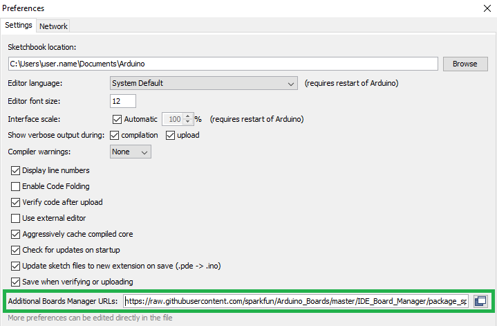
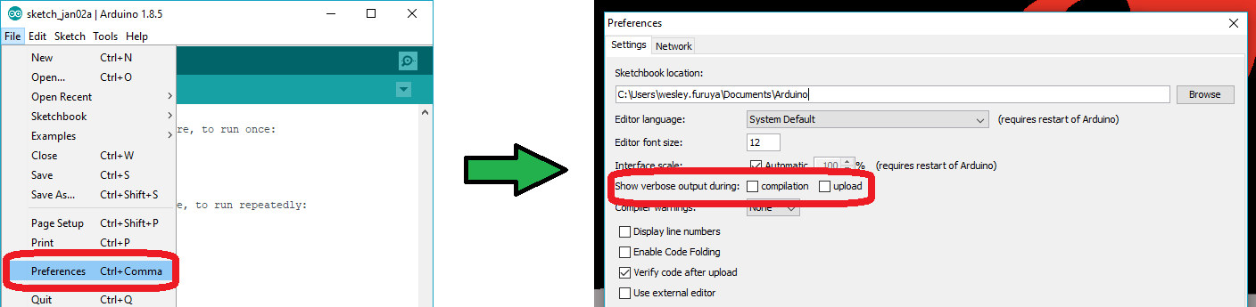
Lets begin by making SparkFun's cores available to the Arduino IDE. This doesn't install the core/board definitions, but it does make them available for ease of use for future installations. Open the Arduino preferences (File > Preferences). Then find the Additional Board Manager URLs text box, and copy the below link in:
https://raw.githubusercontent.com/sparkfun/Arduino_Boards/main/IDE_Board_Manager/package_sparkfun_index.json
For additional details, check out this guide on how cores work in the Arduino IDE.
Install the Arduino SAMD Core
To get a SAMD board working in the Arduino IDE, you'll need to install a variety of tools, including the low-level ARM Cortex libraries full of generic code, the arm-gcc to compile your code, and the Bossa flash utility to upload over the bootloader. These tools come packaged along with Arduino's SAMD board definitions for the Arduino Zero.
To install the Arduino SAMD board definitions, navigate to your board manager (Tools > Board > Boards Manager...), then find an entry for Arduino SAMD Boards (32-bits ARM Cortex-M0+). It may help to enter SAMD into the search bar. Select the Arduino SAMD core and install the latest version (recently updated to v1.6.21).
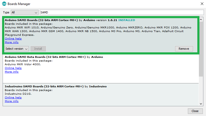
Downloading and installing the tools may take a couple minutes -- arm-gcc in particular will take the longest, it's about 250MB unpacked. Once installed, the INSTALLED text should appear next to the SAMD boards list entry.
Install the SparkFun SAMD Add-on
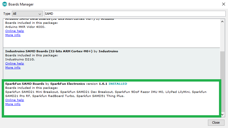
Now that your ARM tools are installed, one last bit of setup is required to add support for the SparkFun SAMD boards. You should be able to find an entry for SparkFun SAMD Boards (dependency: Arduino SAMD Boards 1.6.19) at the end of the SAMD search results. If you don't see it, close the board manager and open it again. Select the add-on package and install the latest version (*recently updated to v1.6.1, but any version after should still work). Again, the INSTALLED text should appear next to the SparkFun SAMD boards list entry.
Select the Board and Serial Port
Once the board definition for the SAMD51 Thing Plus is installed, you should see a new entry in your Tools > Board list under SparkFun SAMD51 Thing Plus.

The bootloader is what allows us to load code over a simple USB interface. To upload code, you will need to manually enter bootloader mode by rapidly double-tapping the reset button. The board will remain in bootloader mode until power cycles, which happens automatically after uploading code.
Double-tapping the reset button to enter bootloader mode.
On the SAMD51 Thing Plus, the there are a clues to if it is in bootloader mode:
- The D13 LED indicator will be a solid blue (may appear to be slowly fading or blinking).
- Board will show up under a different COM port; make sure you select this COM port after the board in the bootloader mode.
- The board will appear as a USB mass storage device under the name 51THINGBOOT.
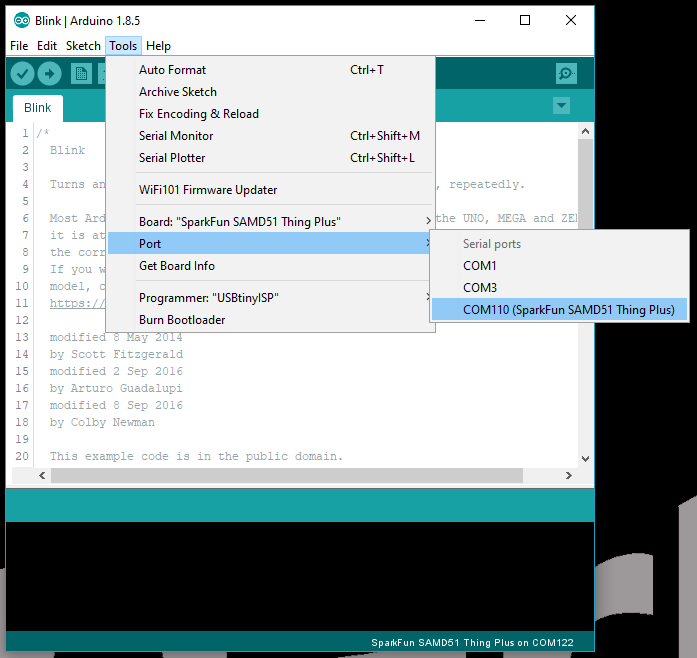
Finally, select your board's port. Navigate back up to the Tool > Port menu. The port menu may magically know which of your ports (if you have more than one) is the SAMD51 Thing Plus board. On a Windows machine, the serial port should come in the form of "COM#". On a Mac or Linux machine, the port will look like "/dev/cu.usbmodem####".
Once you find it, select it! That is all you need to get started in the Arduino IDE. In the next section we will go over the hardware and capabilities of the board. However, if you are eager to upload your first Arduino sketch (and review the hardware information later), you can jump over to the Hardware Assembly and Examples sections.
Hardware Overview
Below is a graphical datasheet for the SAMD51 Thing Plus, which highlights the important features and pin functionality of the SparkFun SAMD51 Thing Plus:
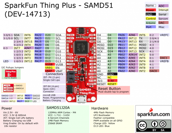
Power/Reset Status LEDs Microcontroller Programming Pin Functions Qwiic Connection Dimensions
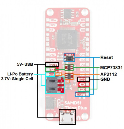
Power/Reset
The SparkFun SAMD51 Thing Plus can be powered via the USB and/or Li-Po battery JST connections. If you choose to power it via USB, the other end of the USB cable can be connected to either a computer or a 5V (regulated) USB wall charger. Otherwise, should you choose to use a Li-Po battery (single-cell only), there is a built in charge circuit to recharge your battery from the USB connection.
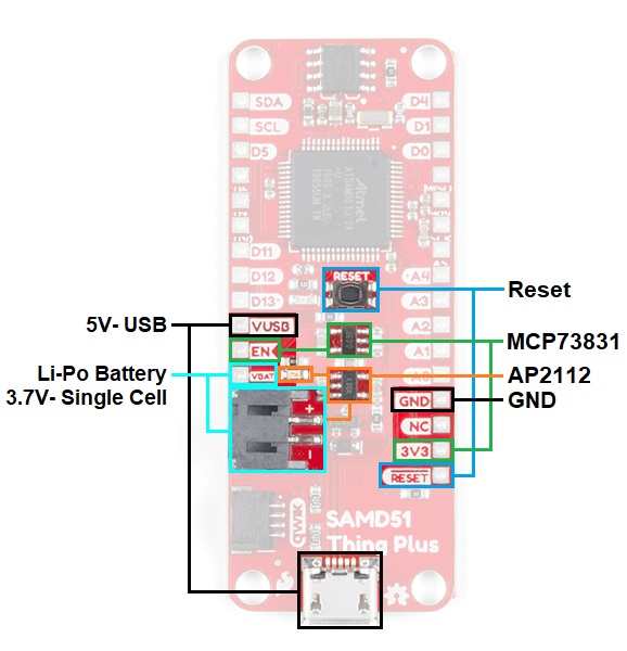
Annotated image of SAMD51 Thing Plus with power and reset features highlighted. Click to enlarge.
USB
A USB micro-B cable is usually the easiest way to power the board, especially when you're programming it because the USB interface is required for uploading code too. Power for the Li-Po battery charging circuit is provided by the USB.
An example of how to pull USB cable straight out from a Qwiic RedBoard.
JST for Li-Po Battery
There is a 2-Pin JST PH connector available for single cell Li-Po batteries. Check out this tutorial for more information on power connectors.
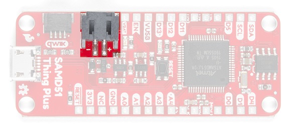
Annotated image of the battery JST connector.
Dual Power
It is fine to connect both a Li-Po battery and a USB connector at the same time. The SparkFun SAMD51 Thing Plus has power-control circuitry to automatically select the best power source. In addition, the charge controller will charge the Li-Po battery from the USB power.
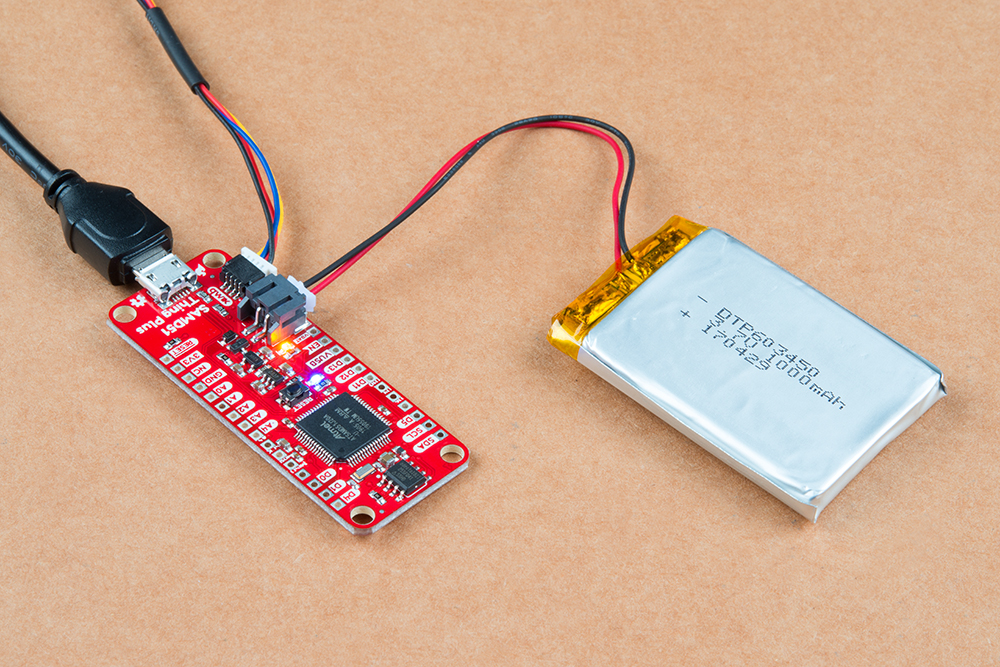
USB and Li-Po battery connected.
MCP73831 Charge Controller
The MCP73831 is a single-cell charge controller. Power for the charge controller comes directly from the USB or VUSB pin. The input voltage range for the MCP73831 is 3.75-6V and it has set charge current of 550mA.
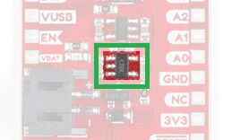
Annotated image of the MCP73831 charge controller.
Charge Indicator LED
Just above the battery JST connector on your circuit board, there’s a tiny LED next to the word VBATT. This yellow LED should light up whenever your battery is charging.
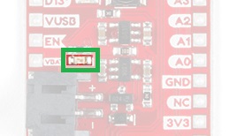
Annotated image of the charge LED.
AP2112 Voltage Regulator
The APA2112 is a robust 3.3V regulator, capable of sourcing up to 600mA from an external voltage of 3.5V to 6V. The external voltage for the APA2112 is provided through the USB and battery connections (also tied to the VUSB and VBATT pins, respectively). The APA2112 regulates 3.3V power to the SAMD51 IC and the Qwiic system. If supplied with less than 3.5V, the power may be unstable; and using more than 6V, the voltage regulator may overheat and damage itself and/or the board.
Annotated image of the AP2112 voltage regulator.
- According to Pete - Voltage Regulators
- Enginursday: Linear Regulator Thermal Tests
- Power and Thermal Dissipation
- Enginursday: Voltage Regulator Temperature Mobile App
Reset Button
Just like the original Nintendo, the board has a reset button. Pushing it will temporarily connect the reset pin to ground and restart any code that is loaded. This can be very useful if your code doesn't repeat, but you want to test it multiple times. Unlike the original Nintendo however, blowing on the Arduino doesn't usually fix any problems.
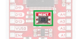
Annotated image of the reset button.
Launch Bootloader Mode
The reset button is used to manually enter and exit bootloader mode. Simply, double-tap the reset button to launch the board into the bootloader (used to program the SAMD51 Thing Plus). The board will remain in bootloader mode until power cycles (happens automatically after uploading code) or the reset button is hit again (once).
Double-tapping the reset button to enter bootloader mode.
Use the indicators below to verify that the board is in bootloader mode:
- The D13 LED indicator will be a solid blue (may appear to be slowly fading or blinking).
- Board will show up under a different COM port.
- The board will appear as a USB mass storage device under the name 51THINGBOOT.
Don't for get to make sure you have the proper serial port selected in the Arduino IDE. The SAMD51 Thing Plus changes to its secondary serial port in bootloader mode.
The Power Pins
There are breakout pins available for all your input/output voltages and reset.
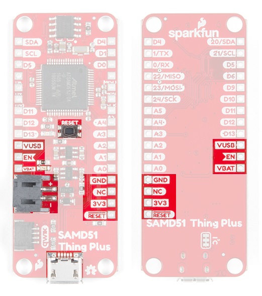
SAMD51 Thing Plus Power Pins
- VUSB- The input voltage to the Arduino board when it's using an external power source. You can provide an external supply voltage through this pin or access the external supply voltage from the power jack through this pin. If only powered through a USB connection, voltage will be around 5V. The input voltage range for this pin is 3.5-6V.
- EN- Tied to Enable pin of the AP2112 voltage regulator.
- VBATT- Provides a connection to the positive terminal of Li-Po battery connector.
- 3V3- The 3.3 volt supply generated by the on-board regulator. Maximum current draw is 600 mA.
- GND- Ground pins.
- RESET- This pin is tied to the Reset pin of the microcontroller and Reset Button. If this pin is toggled low or shorted to the GND pin, it will trigger a reset of the microcontroller.
Status Indicator LEDs
There are 2 status LEDs on the SparkFun SAMD51 Thing Plus, a charge indicator and a test/status LED.

Status LEDs on the SAMD51 Thing Plus.
Charge (Yellow)
This LED indicates that the Li-Po Battery is getting charged. A good secondary test for this status indicator is to use a multimeter to test the VBATT and VUSB pins against the GND pin.
Pin 13 (Blue)
The last indicator is the Pin 13 LED. This is typically only used as a test LED to make sure that a board is working or for basic debugging. However, for the SparkFun SAMD51 Thing Plus, this LED also indicates if the board is in bootloader mode.
- New boards will come programmed with a test sketch that the Pin 13 LED.
Pin 13 is difficult to use as a digital input because of the voltage drop from status LED and resistor soldered in series to it. If the pin is enabled as an input with the internal 20k pullup resistor, it will always read a LOW state; an expected 5V (HIGH) signal will instead read around 1.7V (LOW).
If you must use pin 13 as a digital input, it is recommended that you set the pinMode() as an INPUT and use an external pulldown resistor.
pinMode(13, INPUT);
Microcontroller
The microcontroller (ATSAMD51J20 IC) is the work horse of the SparkFun SAMD51 Thing Plus. The ATSAMD51 is an 32-bit ARM microcontroller manufactured by Atmel, now Microchip. Once an Arduino sketch is uploaded to the board, the program is stored in the memory of the ATSAMD51. The microcontroller will then run/execute the program while the SparkFun SAMD51 Thing Plus is powered.
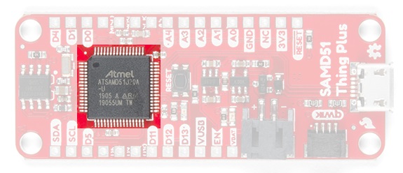
Image of the ATSAMD51 IC.
Clock
An external 32.768kHz crystal is used as the clock for the ATSAMD51. However, the MCU itself has a maximum CPU speed of 120MHz.
Memory
The ATSAMD51 has Flash memory, SRAM (Static Random Access Memory), and backup RAM (Random Access Memory). In addition, there is also 4Mb of external Flash memory.
- 1MB Flash Memory - where the Arduino sketch/program is stored (including the UF2 bootloader).
- 256KB SRAM - where the sketch/program creates and manipulates variables when it runs.
- 4Mb (External) Flash Memory - accessed through SPI.
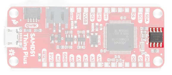
Image of the external Flash memory IC.
The Flash memory is non-volatile; the data is still stored even when the board is no longer powered. The SRAM, on the other hand, is volatile and the data is only available while the board is powered. There is a small bit of SRAM that can retain memory when the SAMD51 is in Standby or Hibernation modes, but that isn't enabled in Arduino yet.
UF2 Bootloader
The bootloader is a unique piece of firmware at the end of the address space of the flash memory. Without a bootloader, you would need to external programmer and program the microcontroller through the SPI interface (normally, the ISP/ICSP headers).
For Arduino users, the UF2 bootloader is BOSSA compatible, which the Arduino IDE expects on ATSAMD boards. Additionally, the UF2 bootloader allows the SAMD51 Thing plus to show up on your computer as a USB storage device.
For more details on the ATSAMD51, memory, and the bootloader check out these tutorials:- Microsoft's GitHub Repository for the (SAMDx1) UF2 Bootloader
- Arduino Memory Tutorial
- Arduino Bootloader Page
- Arduino as ISP and Arduino Bootloaders
- StackExchange Forum Post on Bootloaders
Bootloader Mode to Program
As mentioned previously, you will need to manually enter bootloader mode (by double-tapping the reset button) to program the SAMD51 Thing Plus. Once the Arduino IDE is finished programming the board, it should automatically exit the bootloader by resetting the board.
Double-tapping the reset button to enter bootloader mode.
Use the indicators below to verify that the board is in bootloader mode:
- The D13 LED indicator will be a solid blue (may appear to be slowly fading or blinking).
- Board will show up under a different COM port.
- The board will appear as a USB mass storage device under the name 51THINGBOOT.
Don't for get to make sure you have the proper serial port selected in the Arduino IDE. The SAMD51 Thing Plus changes to its secondary serial port in bootloader mode.
Programming
There are two ways to program the SparkFun SAMD51 Thing Plus. The most common way for users is through the USB connection. The other slightly less common method is through the ISP headers or pins.
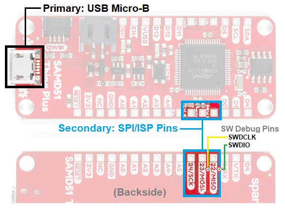
SAMD51 Thing Plus programming connections.
USB Connection
The USB micro-B connector is the most convenient way to power and program the board. To program the board through the USB connection, you will need a USB micro-B cable and there must be a bootloader flashed to the microcontroller (don't worry... we have already "factory installed" one). For the SparkFun SparkFun SAMD51 Thing Plus, this is a UF2 bootloader similar to the [RedBoard Turbo](https://www.sparkfun.com/products/14812). Most users will program the SAMD51 Thing Plus through a USB connection with the Arduino IDE.
Troubleshooting Tip: Users should take care NOT to pry or leverage on the connector when inserting/removing the USB cable. Doing so, WILL damage the board and cause the pads and/or traces to tear off as well. The cable should be removed by pulling straight outwards from the board.
An example of how to pull USB cable straight out from a Qwiic RedBoard.
Bootloader Mode to Program
The bootloader is what allows us to load code over a simple USB interface. When using the Arduino IDE, the board needs to be manually launched into the bootloader prior to any attempts to upload a sketch. To manually enter bootloader mode, rapidly double-tapping the reset button (after hitting the reset button once, you have about half a second to hit it again). The board will remain in bootloader mode until power cycles (happens automatically after uploading code) or the reset button is hit again (once).
Double-tapping the reset button to enter bootloader mode.
Use the indicators below to verify that the board is in bootloader mode:
- The D13 LED indicator will be a solid blue (may appear to be slowly fading or blinking).
- Board will show up under a different COM port.
- The board will appear as a USB mass storage device under the name 51THINGBOOT.
Don't forget to make sure you have the proper serial port selected in the Arduino IDE. The SAMD51 Thing Plus changes to its secondary serial port in bootloader mode.
Using SPI pins for ISP or ICSP Programming
The least common way for most users to program the microcontroller on their board, is to use the Serial Peripheral Interface (SPI) pins for in-system programming (ISP). A more experienced user, with a firm grasp on digital electronics and the microcontroller (datasheet), will probably use a software package like Atmel studio, which is easier to debug code through the available software debug pins.
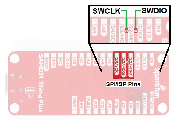
Annotated image of programming and debug pins.
The most common reasons for programming with this method are:
- ISP is faster and more reliable- We use this method in our QC process for most boards.
- There is no bootloader on the microcontroller or your board wasn't flashed properly:
- This is probably the only way to program the microcontroller without a bootloader.
- You want to use your own, custom bootloader.
- Configure fuse bits for various settings.
- Program without bootloader, when you need just a little bit more space for your program to load.
Pin Functions
All of the SparkFun SAMD51 Thing Plus's pins are broken out to 0.1" spaced through holed on the outer edges of the board.Power Pins
The power pins aren't really I/O (Input/Output) pins for the microcontroller; however, they are pertinent to the board. For more details on these pins, see the Power/Reset tab.
SAMD51 Thing Plus power pins.
The pins mostly operate as voltage supply pins. These pins are traditionally used as power sources for other pieces of hardware (like LEDs, potentiometers, and other circuits).
- 3.3V- A regulated 3.3V voltage source.
- VUSB- The (normally 5V) voltage from the USB connection.
- VBAT- The voltage from the Li-Po battery connection. Usually, used for checking remaining charge on battery.
- GND- The common ground or the 0V reference for the voltage supplies.
- EN- Tied to Enable pin of the AP2112 voltage regulator.
- RESET- The RESET pin can be shorted to the GND pin to reset the microcontroller, similar to using the reset button.
Microcontroller I/O Pins
All of the I/O pins on this board are digital inputs or outputs for the microcontroller (ATSAMD51J20). Most pins are configurable for other capabilities.
Digital I/O
There are 21 I/O pins on this board, which can be operate as either digital inputs or outputs for the microcontroller (ATSAMD51). This includes the pins labeled as Analog, which may be configured and used in the same manner as the digital pins. Digital pins are what you connect to buttons, LEDs, sensors, etc. to interface the Arduino with other pieces of hardware.
Input
By default, all digital I/O pins are configured as inputs. It is best practice to define the pinMode() in the setup of each sketch (programs written in the Arduino IDE) for the pins used. When configured properly, an input pin will be looking for a HIGH or LOW state. Input pins are High Impedance and takes very little current to move the input pin from one state to another.- If an input pin is read and that is floating (with nothing connected to it), you will see random data/states. In practice, it may be useful to tie an input pin to a known state with a pullup resistor (to VCC), a pulldown resistor (to GND), or configure the pin as a pull-up/down input.
- Pin 13 is difficult to use as a digital input because of the voltage drop from status LED and resistor soldered in series to it.
Output
When configured as an output the pin will be at a HIGH or LOW voltage. Output pins are Low Impedance: This means that they can provide a substantial amount of current to other circuits.The maximum current an I/O pin can source (provide positive current) or sink (provide negative current) is .5 - 8 mA (milliamps). For more details, you can refer to the ATSAMD51 datasheet. Attempting to run high current devices may damage the pin or entire ATSAMD51 chip.
Additional Functions
There are several pins that have special functionality in addition to general digital I/O. These pins and their additional functions are listed in the tabs below. For more technical specifications on the I/O pins, you can refer to the ATSAMD51 datasheet or the below table, which outlines which SERCOM ports each pin has been conected to (shown in green) along with the available SERCOM Ports. For more information on SERCOM and how it can help you with your hardware peripherals, check out our guide here.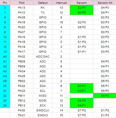
Analog Input Pins
There are 6 labeled analog inputs. These pins tie to a 12-bit (12-bit = 4096 different values) analog to digital converter (ADC), which can be used to read in an analog voltage between 0 and 2.82V or VCC (depending on the configuration). These are useful if you need to read the output of a potentiometer or other analog sensors.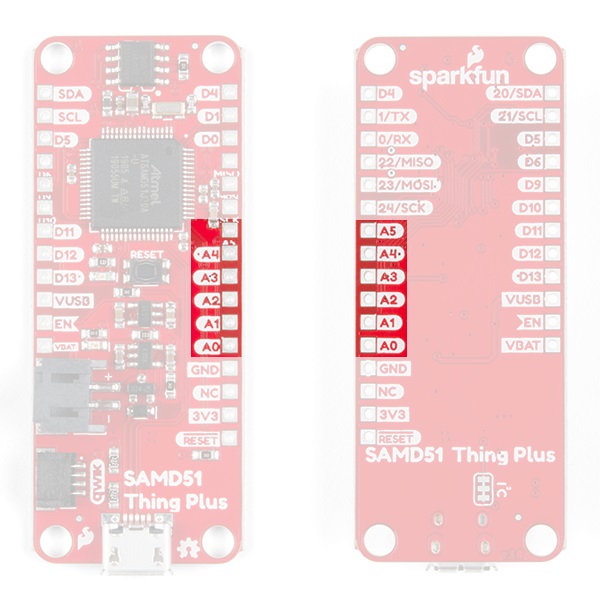
SAMD51 Thing Plus analog input pins. Click to enlarge.
For more details on the analog inputs, check out these tutorials:
Pulse Width Modulation (PWM) Output Pins
Digital pins can be configured as 24-bit PWM capable outputs, which you can use to dim LEDs or run servo motors.Novice users often mistake PWM pins as an analog output. Although, it can somewhat mimic that functionality, it is not a true analog output.
Serial Communication Pins
Digital pins 0 (RX) and 1 (TX) are also dedicated serial communication pins. These pins are used to receive (RX) and transmit (TX) TTL serial data. Other digital pins can be use to emulate serial communication with SoftwareSerial().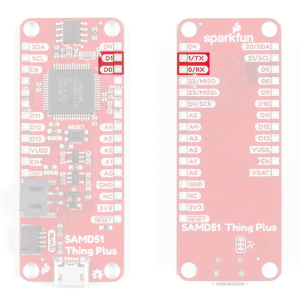
SAMD51 Thing Plus dedicated serial communication pins. Click to enlarge.
For more details on serial communication, check out these tutorials:
SPI Communication Pins
Digital pins 23 (MOSI), 22 (MISO), and 24 (SCK) support Serial Peripheral Interface (SPI) communication. (The slave select (SS) pin is user defined.)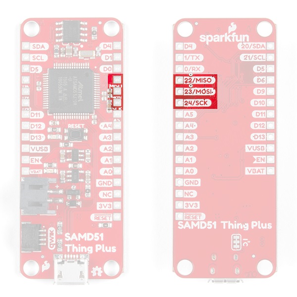
SAMD51 Thing Plus SPI pins. Click to enlarge.
Using the Serial Peripheral Interface, configures the SCK and MOSI pins to be directly managed by the SPI hardware. Therefore, while in use, pins 11 and 13 can't be used (i.e. the LED on pin 13 can no longer be used as a debug/status indicator.)
Executing "SPI.end();" allows those pins 11 and 13 to be used as general I/O again.
I2C Communication Pins
Analog pins 20 (SDA) and 21 (SCL) support I2C (TWI) communication.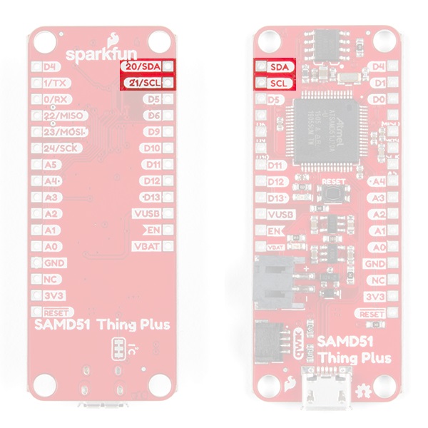
SAMD51 Thing Plus I2C pins. Click to enlarge.
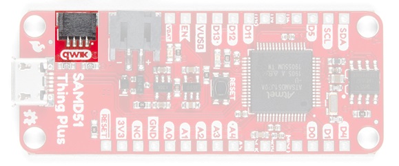
Qwiic System
The Qwiic system is intended a quick, hassle-free cabling/connector system for I2C devices. The Qwiic connector is tied to the I2C pins.
Be sure to double check that you are not trying to use an I2C device while you are trying use pins 20 and 21, you will run into issues. You can only do one or the other.
Interrupt Pins
Interrupts allow you to interrupt the code running in your main loop and execute another set of instructions (also known as interrupt handler or interrupt service routine) before returning back to the main loop. For more details on the interrupts, check out these tutorials:Qwiic Connector
The most convenient feature of the board is the Qwiic connector that allows the SparkFun SAMD51 Thing Plus to seamlessly interface with SparkFun's Qwiic Ecosystem.
What is Qwiic?
The Qwiic system is intended a quick, hassle-free cabling/connector system for I2C devices. Qwiic is actually a play on words between "quick" and I2C or "iic".
Keep your soldering iron at bay.
Cables plug easily between boards making quick work of setting up a new prototype. We currently offer three different lengths of Qwiic cables as well as a breadboard friendly cable to connect any Qwiic enabled board to anything else. Initially you may need to solder headers onto the shield to connect your platform to the Qwiic system but once that’s done it’s plug and go!

Qwiic cables connected to Spectral Sensor Breakout
Minimize your mistakes.
How many times have you swapped the SDA and SCL wires on your breadboard hoping the sensor will start working? The Qwiic connector is polarized so you know you’ll have it wired correctly, every time, from the start.
The PCB connector is part number SM04B-SRSS (Datasheet) or equivalent. The mating connector used on cables is part number SHR04V-S-B or equivalent. This is a common and low cost connector.

1mm pitch, 4-pin JST connector
Expand with ease.
It’s time to leverage the power of the I2C bus! Most Qwiic boards will have two or more connectors on them allowing multiple devices to be connected.

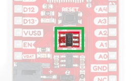
Pull-Up Jumpers
These jumpers can be cut to disconnect the 2.2kΩ pull-up resistors from the I2C bus. You only need to cut this trace if you have a bunch of devices with pull-up resistors because the pull up becommes too strong.
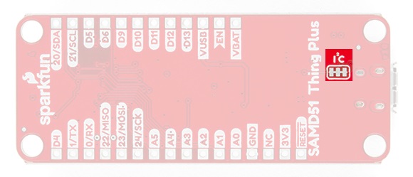
Jumper for pull-up resistors.
How to Modify the Pull-Up Jumper
You will need a knife to modify the jumpers. To modify the jumper, located on the back of the board next to the Qwiic connector, you need to cut the trace between the two pads. Once you have cut the trace, the pull-up resistors will be disconnected. To repair the connection, you just need to solder a jumper between the pads of both jumpers. Be sure to test the jumper with a multimeter to make sure you have a good soldered connection.
Adding External Power
If you need more power for your Qwiic devices, you can attach a separate power supply. However, it is recommended that you cut the 3.3V line of the Qwiic cable to the SparkFun SAMD51 Thing Plus. Leave the GND line alone, as that ground loops your system, providing a consistent reference voltage for your I2C signals.
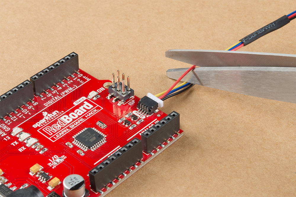
Cutting the 3.3V line of the Qwiic cable to the Qwiic connector (on a Qwiic RedBoard).
By cutting the 3.3V line, this allows you to power all your devices without straining the 3.3V regulator on the board. Since, all voltage regulators are slightly different and don't maintain a perfect 3.3 voltage, the 3.3V AP2112 regulator would be constantly battling the voltage regulator of your separate power supply to regulate its version of 3.3V. For more details on voltage regulators, check out this According to Pete blog post.
Dimensions
The dimensions for the board are approximately 0.9" x 2.3". The breakout pins use a standard 0.1" spacing and the layout is compatible with Feather styled shields. There is a 2-Pin JST PH connector for the option to add Li-Po batteries. The Qwiic connector uses a 4-pin JST SH type connector. There are also 4 mounting points on the board.
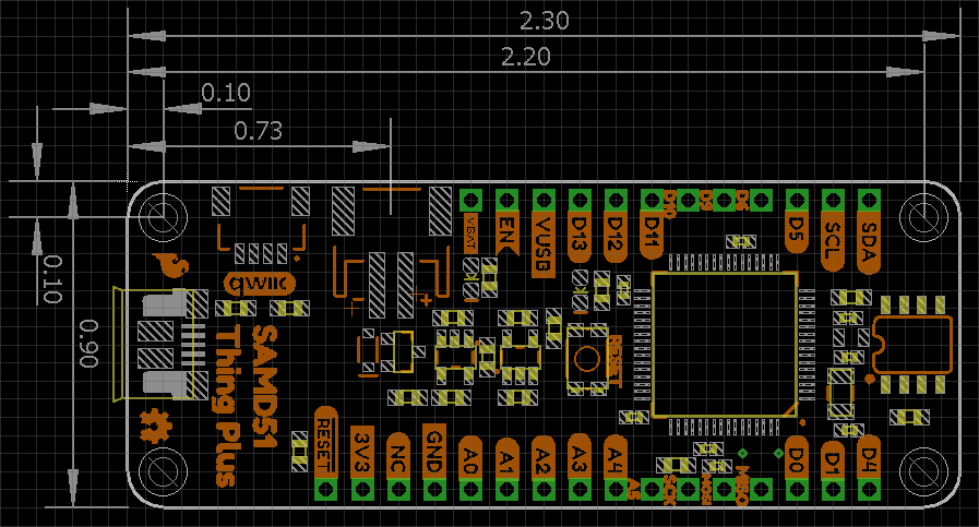
Screen shot of SAMD51 Thing Plus board layout in Eagle. (Click image to enlarge.)
For the more details on the board sizing and component placement please refer to the Eagle files provided.
Eagle is a free for educators, makers, and hobbyists (i.e. basically, anything not for commercial purposes). All measurements are accurate, excluding any manufacturing tolerances. (Unfortunately, we do not have this information available; you may need to just measure the board you purchase.)
Hardware Assembly
Connectors
The SAMD51 Thing Plus has 3 primary connectors a micro-B USB connection, a Qwiic connector, and a battery JST connector.
Micro-B USB Connector
There are a few ways to use this board. However, most users will be interfacing with the SAMD51 Thing Plus, primarily through the micro-B USB connector to power and program the board. This connection is also used to charge the Li-Po battery, when in use. Need another micro-B USB cable for your drawer?
Qwiic Connector
With the Qwiic connector system, assembling your hardware is simple. All you need to do is connect your Qwiic device to the SAMD51 Thing Plus with a Qwiic cable.
JST Battery Connector
There is a 2-Pin JST PH connector available for single cell Li-Po batteries. The SAMD51 Thing Plus also has a built-in charge controller for charging your single cell Li-Po battery from the USB connection.
Headers & Shields
All the pins for the SparkFun SAMD51 Thing Plus are broken out to 0.1"-spaced pins on the outer edges of the board. When selecting headers, be sure you are aware of the functionality you need. If you have never soldered before or need a quick refresher, check out our How to Solder: Through-Hole Soldering guide.
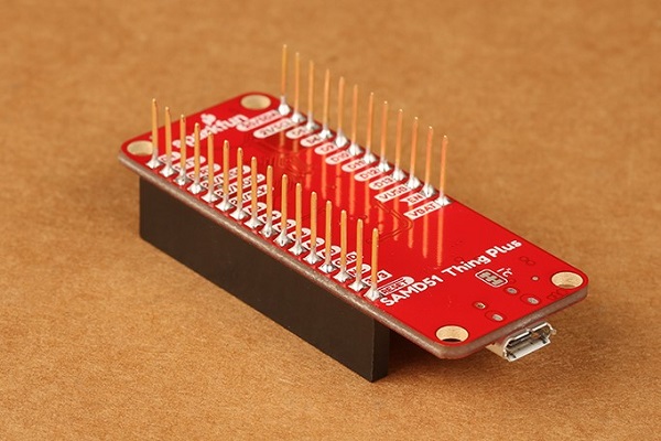
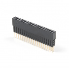
The Feather Stackable Header Kit is a great option as it allows users to stack shields (w/ Feather footprint) or it can be placed on the a breadboard; while, the pins are still accessible from the female/male headers.

Arduino Examples
In this section, we will run a few simple sketches to verify and demonstrate the board's functionality.
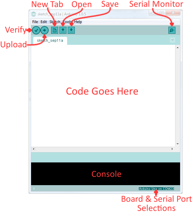
Using the Arduino IDE
Now it's finally time to upload code to your SAMD51 Thing Plus in the Arduino software. Once you open up the application, you'll be presented with a window that looks a little something like this:
Before we can send the code over to the SAMD51 Thing Plus, there are a couple of adjustments we need to make.
Select a Board
If you haven't already selected the proper board from the Arduino IDE setup section earlier, we will go over it again. This step is required to tell the Arduino IDE which of the available Arduino boards, we are using. Go up to the Tools menu, hover over Board, and be sure to select the SparkFun SAMD51 Thing Plus from the drop-down list.
Select a Serial Port
The bootloader is what allows us to load code over a simple USB interface. To upload code, you will need to manually enter bootloader mode by rapidly double-tapping the reset button. The board will remain in bootloader mode until power cycles, which happens automatically after uploading code.
Double-tapping the reset button to enter bootloader mode.
On the SAMD51 Thing Plus, the there are a clues to if it is in bootloader mode:
- The D13 LED indicator will be a solid blue (may appear to be slowly fading or blinking).
- Board will show up under a different COM port; make sure you select this COM port after the board in the bootloader mode.
- The board will appear as a USB mass storage device under the name 51THINGBOOT.
Next up we need to tell the Arduino IDE which of our computer's serial ports the SAMD51 Thing Plus is connected to. Navigate back up to the Tools > Port menu. The port menu may magically know which of your ports (if you have more than one) is the SAMD51 Thing Plus board. On a Windows machine, the serial port should come in the form of COM#. On a Mac or Linux machine, the port will look like /dev/cu.usbmodem####.
Once you find it, select it! If you've got more than one port, and you're not sure which of the serial ports is your SAMD51 Thing Plus, unplug it for a moment and check the menu to see which one disappears.
Example 1: Uploading Blink
In this example we will go over the basics of the Arduino IDE and upload a sample code. This is a great way to test the basic functionality of any board to make sure it is working.Example 1: Blink
Blink Sketch
Code written for the Arduino IDE are referred to as sketches. All code in Arduino is C based. Let us upload a Blink sketch to make sure our new RedBoard setup is totally functional. Go up to the File menu in Arduino, then go to Examples > 01.Basics > Blink to open it up.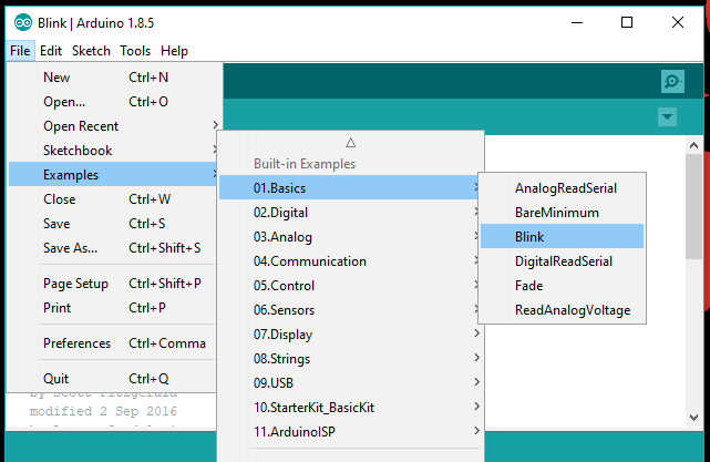
Screen shot of Blink sketch selection.
Upload!
With all of those settings adjusted, you're finally ready to upload some code! Click the Upload button (the right-pointing arrow) and allow the IDE some time to compile and upload your code. It should take around 30 seconds for the process to complete. When the code has uploaded, you should see something like this in your console window: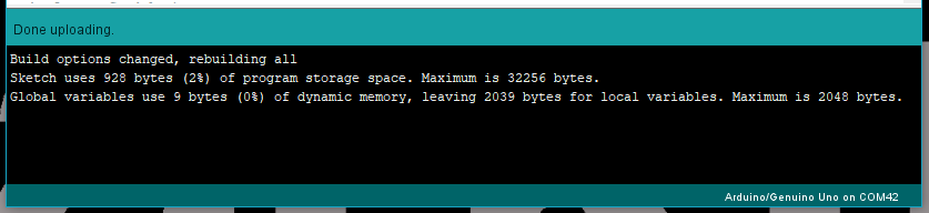
Screen shot of upload complete.
And if you look over to the SAMD51 Thing Plus, you should see the blue LED turn on for a second, off for a second, on for a second, off for a second...ad infinitum (at least until it loses power).
If you want to adjust the blink speed, try messing with the "1000" value in the delay(1000); lines. You're well on your way to becoming an Arduino programmer!
Something Wrong?
Uh oh! If you didn't get a "Done Uploading" message, and instead got an error, there are a few things we can double-check.If you got an avrdude: stk500_getsync(): not in sync: resp=0x00 error in your console window.
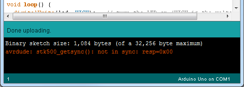
Screen shot of Error Message in the Console.
Either your serial port or board may be incorrectly set. Again, make sure SparkFUN SAMD51 Thing Plus is the board selection (under the "Tools > Board" menu). The serial port is usually the more common culprit here. Is the Serial Port correctly set (under the "Tools > Serial Port" menu)? Did the drivers successfully install? To double check your board's serial port, look at the menu when the board is plugged in, then unplug it and look for the missing port. If none of the ports are missing, you may need to go back to driver verification.
Troubleshooting
Below, we have also included some troubleshooting tips for issues that you may come across with the new SAMD51 Thing Plus.
- One of our employees compiled a great list of troubleshooting tips based on the most common customer issues. This is the perfect place to start.
- For any Arduino IDE specific issues, I recommend starting with their troubleshooting guide.
If neither of the troubleshooting guides above were able to help, here are some additional tips:
Dual Serial Ports
One global issue to be aware of is that each SAMD51 Board appears to your computer as two USB devices, and your computer will assign two different port numbers to your SAMD51 Board - one for the bootloader, the other for the sketch.
- Verify that you are selecting the available serial port for the board.
- If your computer isn't registering the board try double-tapping it into bootloader mode.
- Once the Arduino IDE is finished programming the board, it should automatically exit the bootloader by resetting the board. (At that point, the board will be on a different serial port, from the one it was programmed on.)
My Board Isn't Working in Arduino:
Every board that we manufacture gets tested. If you didn't buy the board from us or one of our authorized distributors, it could be a knock-off. That being said, let's try a basic test to see if just the board is working. Disconnect everything that you have attached to the board; we just want to test the board.
- Inspect the board:
Check the board to make sure everything looks about right. Use the pictures on the product page to verify component placement or alignment, and bad solder joints, or damage. - Power and check the LEDs:
Using a known good USB micro-B cable, plug your board in to the computer. Do any of the LEDs turn on (see Hardware Overview)?- New boards will come programmed with board in bootloader mode. The pin 13 should be slowly blinking/fading in and out (may look like a solid blue).
- Put the board in bootloader mode:
Double-tapping the reset button to enter bootloader mode.To enter bootloader mode, rapidly double-tap the reset button. On the SAMD51 Thing Plus, the there are a clues to if the board is in bootloader mode:- The D13 LED indicator will be a solid blue (may appear to be slowly fading or blinking).
- Board will show up under a different serial port.
- The board will appear as a USB mass storage device under the name 51THINGBOOT.
- Upload the Blink sketch:
Try to upload a blink sketch. Why blink? It is simple, known to work (from the example files), and you have an indicator LED.- Double check that you have the proper Board and Serial Port selected.
- For boards that are already running the blink example, I recommend changing the timing parameters to check for a change in the board's response.
- Verify Functionality:
Check that you see the pin 13 LED blinking properly and that the Arduino IDE shows a status of Done uploading.
I Don't See My Board on a Serial/COM Port:
If you don't see your board as an available COM port on the Arduino IDE:
- Try to re-open the Arduino IDE.
- Check the Device Manager:
Verify that your computer recognizes the board. See the Driver Verification section of the tutorial. - Check that you are using a USB cable capable of data transfers:
Your issue might be related to your USB cable; some cables only have the power pins connected for charging. A good way to test this is to plug in a device to your USB cable (like a phone). If it doesn't show up as a device or drive, then try a new USB micro-B cable. - Try forcing the board between the dual serial ports:
- Bootloader Mode:
Double-tapping the reset button to enter bootloader mode.To enter bootloader mode, rapidly double-tap the reset button. On the SAMD51 Thing Plus, the there are a clues to if the board is in bootloader mode:- The D13 LED indicator will be a solid blue (may appear to be slowly fading or blinking).
- Board will show up under a different serial port.
- The board will appear as a USB mass storage device under the name 51THINGBOOT.
- USB Serial Port:
The board will remain in bootloader mode until power cycles (happens automatically after uploading code) or the reset button is hit again (once).
- Bootloader Mode:
- Try a different USB port:
This rarely happens, but it is easy to check. If you are using a USB 3.0 port (you will see a blue "tongue" in the USB jack or bad USB port, try a different USB port. You can also try to test the board on a different computer to double check for a hardware incompatibility (usually with expansion boards).
Errors Uploading to the Board:
There are two types of issues that you will usually see in the console of the Arduino IDE, compile errors or upload errors. The easiest way to see where to start is by clicking the Verify button (check mark); the Arduino IDE will try to compile your code. A failure here is a compile error.
It takes a some experience, but if you enable the verbose output from the Arduino IDE preferences, it may give you more clues to where the issue is.
- Compile Errors:
With compile errors, there are several things that could be causing issues. However, 99% of the time, it is user error. Usually something wrong with your code or the library you are using. Once in a while you will have a file structure issue if you manually added a file/folder in any of the Arduino folders (still user error). - Upload Errors:
Upload errors get a little more tricky. You will usually just see the Arduino IDE trying to upload to the board multiple times. There are usually several different causes for this, often without specific errors in the console. Here are a few common examples:- Wrong Board Selection:
Double check you board selection options. If you uploaded with the wrong board selection, there is a small chance that you may have overwritten the bootloader on the board or damaged the microcontroller. - Not Accessing the Bootloader:
If a sketch upload is taking longer than usual, or fails entirely, try resetting into the bootloader mode and uploading directly there. If the SAMD51 is in bootloader mode, you may need to re-select your port (see Dual Serial Port section above). - Serial Port Interference:
Closing the serial monitor before uploading may also be more reliable uploading. - Bad USB cable or port.
- Wrong Board Selection:
If have gone through all the troubleshooting tips you and are still having issues or if you have questions about the product, please create a post on our forum.
Resources and Going Further
Now that you've successfully got started with your SAMD51 Thing Plus, it's time to incorporate it into your own project! For more information, check out the resources below:
- Schematic (PDF)
- Eagle Files (ZIP)
- ATSAMD51 Datasheet (PDF)
- Graphical Datasheet (PDF)
- Qwiic Landing Page
- GitHub Hardware Repo
- Product Showcase
Need some inspiration for your next project? Check out some of these related tutorials:
SparkFun Tutorials
Installing an Arduino Library
What is an Arduino?
Installing Arduino IDE
Arduino Board Comparison Guides
Hookup Guides for Other SAMD Boards
Choosing an Arduino for Your Project
Standard Arduino Comparison Guide
SAMD21 Mini/Dev Breakout Hookup Guide
RedBoard Turbo Hookup Guide
Click the buttons above for tutorials relating to the board functionality based on topic difficulty.
Beginner
Serial Communication
Analog to Digital Conversion
Analog vs. Digital
Data Types in Arduino
How to Work with Jumper Pads and PCB Traces
Intermediate
Serial Peripheral Interface (SPI)
Processor Interrupts with Arduino
Adding More SERCOM Ports for SAMD Boards
Advanced
Installing an Arduino Bootloader
Integrated Circuits
Reading and Writing Serial EEPROMs
Looking for project ideas? Check out some of these Qwiic products and tutorials:
Qwiic Pro Kit Project Guide
Advanced Autonomous Kit for Sphero RVR Assembly Guide
Getting Started with the Autonomous Kit for the Sphero RVR
SparkFun Top pHAT Hookup Guide
Or check out this blog post for ideas: