Secure DIY Garage Door Opener
 QCPete
Introduction
If you'd like to increase the security of your garage door, or you are just interested in learning more about cryptography, then read on! At its core, this project is simply about a secure wireless button. This could be used to trigger any number of things, so we hope it can inspire message security on many other future projects.
I was surprised to learn that even if your garage door is fairly new, then you may still be vulnerable to man-in-the-middle or roll-jam attacks. With this tutorial, you can achieve an extremely high level of security utilizing ECC signatures and the SparkFun Cryptographic Co-processor.
If you'd like to read more about garage doors, here are two great articles about hacking and history.
During my research for this project, I also came across an interesting story about garage doors in San Francisco. In 2004, military radio signals were jamming garage door openers. It seems that most garage door openers at the time were operating on the same frequency as a new military communications system (390 MHz). For more details, check out this CBS News article. After learning this, I was glad to know that my new setup is operating on 915MHz, and so it shouldn't be effected.
Most communication channels are exposed to the world. Whether it's a hard wired connection or a wireless signal flying through the air, anyone can listen in and try to intercept, record, and/or impersonate your signal. So how do we protect ourselves against these malicious attacks? Surprisingly, you can make a very robust solution with a couple of Pro RFs and our Cryptographic Co-processors.
Suggested Reading
If you aren’t familiar with the following concepts, we recommend you read over these tutorials before continuing.
Serial Communication
SparkFun SAMD21 Pro RF Hookup Guide
Qwiic Single Relay Hookup Guide
Three Quick Tips About Using U.FL
Cryptographic Co-Processor ATECC508A (Qwiic) Hookup Guide
The Secure Solution
We are going to use digital signatures to add security to our system. If you want to learn more about how to use the Cryptographic Co-processor, check out the hookup guide and associated video. These will show you the fundamental ideas behind digital signatures, walk you through how to setup each co-processor.
Cryptographic Co-Processor ATECC508A (Qwiic) Hookup Guide
October 17, 2019
For the secure garage door opener example shown here, we are going to do something very similar to Example 6 in the Arduino Library. A complete cycle will follow these steps:
- User presses button on remote to engage cycle.
- Remote sends a "request for token".
- Base generates a new random token (32-bytes).
- Base sends token to remote.
- Remote creates ECC signature on token (using its unique private key).
- Remote sends ECC signature to base.
- Base verifies signature using remote's public key.
- If verified, base opens garage.
What makes this so secure is the fact that the only place in the world that can create a valid signature is inside the remote's co-processor. This is because the private key was generated randomly during configuration and will never leave the IC. If you don't have that actual piece of hardware (the remote co-processor), you will never be able to create a signature.
Also, the fact that the base creates a new random token for each cycle, allows us to prevent against man-in-the-middle and roll-jam attacks.
Wahoo! That's one heck of a secure wireless button!
Hardware Overview
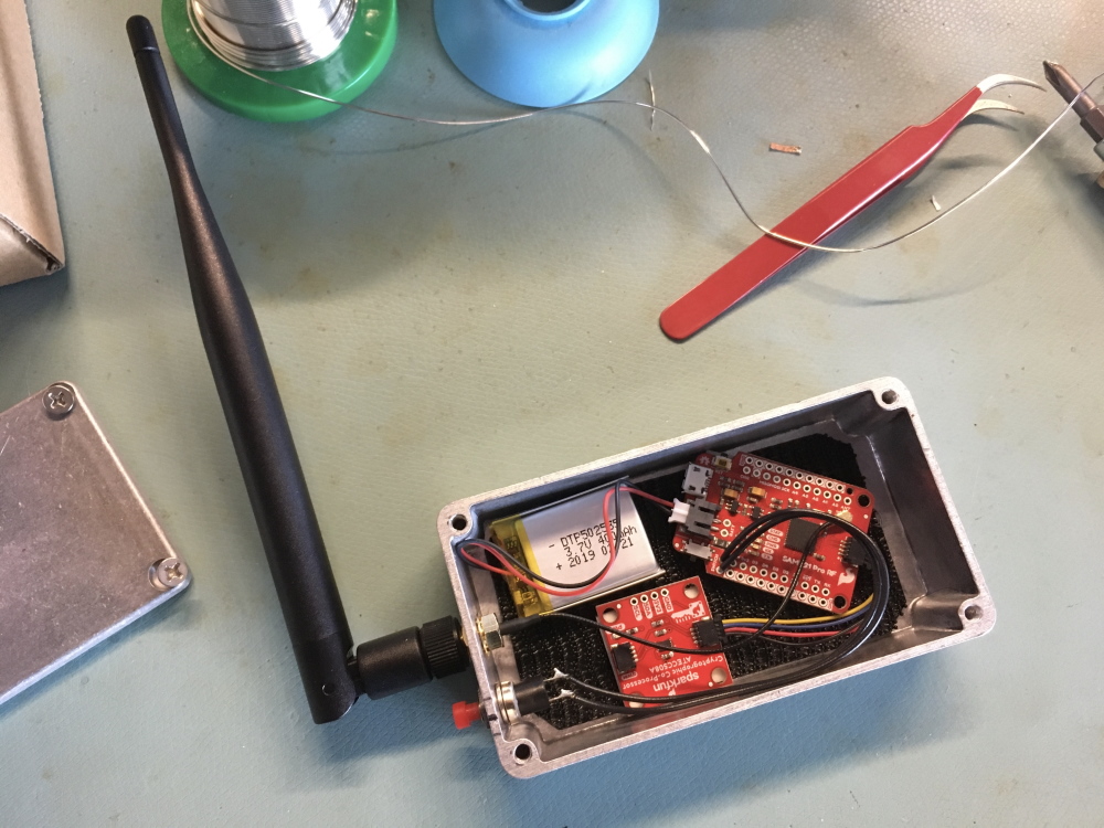
For this project, we need to build up two separate circuits. One will be the remote control (that lives in my car or bike), and the second will be the base transceiver that lives inside my garage (listening for the ECC signature, and then engaging the garage door button).
Remote Control
- Pro RF
- Duck Antennae
- Cryptographic Co-processor (for creating the ECC signature)
- Enclosure
- Button
- 400mAh Lipo Battery
- Qwiic Cable (QTY:1)
Base Transceiver
- Pro RF
- Wire antennae
- Cryptographic Co-processor (for creating the TTL token, and verifying the ECC signature)
- SparkFun Qwiic Single Relay
- Wire antennae
- USB wall wart
- Qwiic Cable (QTY:2)
For easy one click ordering, here is a wish list. Be sure to read the entire tutorial, and then adjust as necessary.
Hardware Hookup
All of these boards use Qwiic, so that made things much easier and faster to hookup.
The Remote
For the remote control, there are only 4 connections that need to be made:
| From/Device 1 | Connection Type | To/Device 2 | |
| 1. | Pro RF | Qwiic Cable | Cryptographic Co-processor |
| 2. | LiPo Battery | JST | Pro RF |
| 3. | Duck Antennae | U.FL to SMA adapter cable | Pro RF |
| 4. | Button | Wire | Switch Headers on Pro RF |
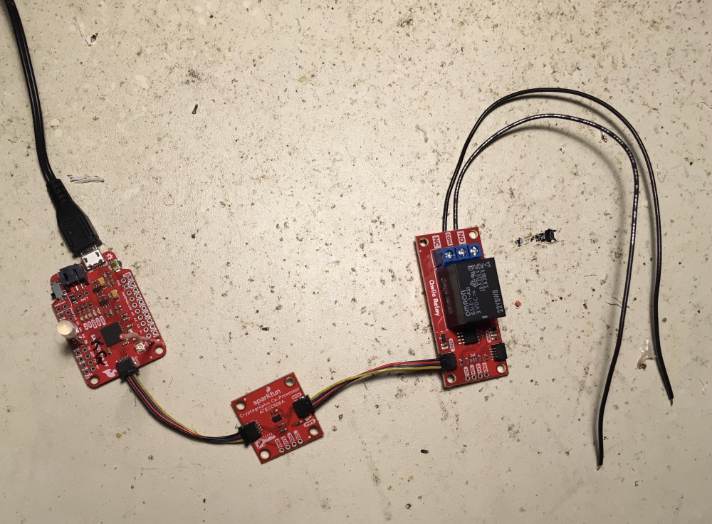
The Base Transceiver
The Base Transceiver also requires hooking up just 4 connections:
| From/Device 1 | Connection Type | To/Device 2 | |
| 1. | Power adapter | USB | Pro RF |
| 2. | Pro RF | Qwiic Cable | Cryptographic Co-processor |
| 3. | Cryptographic Co-processor | Qwiic Cable | Relay |
| 4. | Relay COM & NO | Wire | Garage door button |
Note, the order of boards in the qwiic system didn't matter, but I put the relay last so I could position it for easier access. I also soldered to the PTH pins on the bottom of the screw pin terminal, but you could choose to do a solderless connection if you like.
Integration
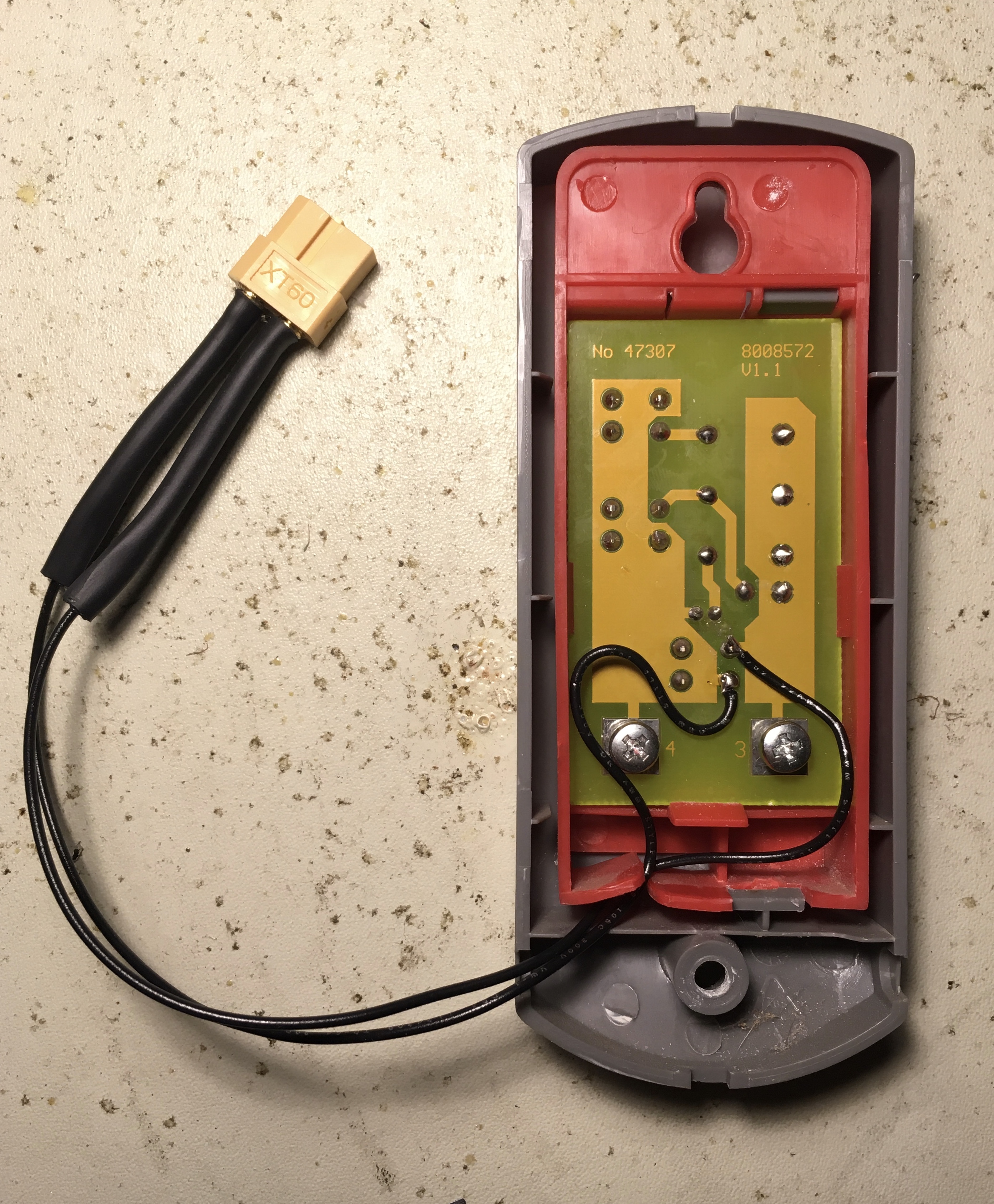
To engage the garage door, I opted to emulate what a human does (press the button on the wall inside). I opened up the wall-mounted controller and saw this:
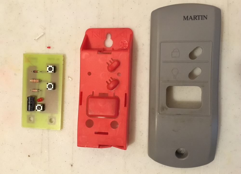
Aha! I recognize those mini push button switches.Upon further inspection, I saw that there are various passive components involved:
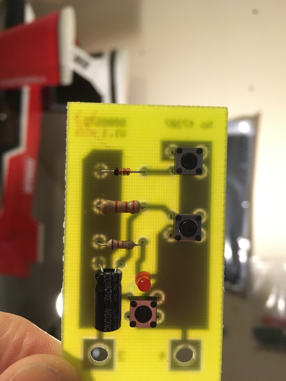
Pretty neat how they are able to get three button control from simply two wires. I wonder if there is an ADC involved? Or maybe some sort of pulsing and time sensitive digital reads? Maybe an AC signal? What do you think?
For this project, I was only concerned with the lower momentary switch (aka the "big button"). From looking at the circuit board with backlight as shown above, I was able to see that the lower button simply connects the two leads together directly without any extra passives involved. With this in mind, I decided to use a relay and run it in parallel with the switch. I used a SparkFun Qwiic Single Relay to engage this button from my Arduino. I know this is probably overkill for the amount of current this will ever see, but I liked that this solution would be very easy to connect/control using Qwiic and was a sure bet in emulating the button.
For the connection to the garage door wall-mounted button, I chose to open it up and solder to the connection points on either side of the button. After doing so, I actually realized that you could "tap" into the two wires out to the button anywhere in the line and potentially use the screw pin terminals on the relay for a solder-less connection point. Nevertheless, I used a couple XT-60 connectors on the lines, and this makes it pretty easy to take apart if necessary for re-programming.
Power Considerations
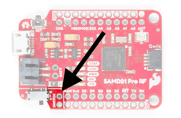
In order to save power on the remote control, I opted to put a momentary push button in series on the power input. This way, power would only be connected when I wanted to open the garage door. Otherwise, it would remain completely off. Also, with a more traditional DPST switch, we'd be more likely to accidentally leave it switched on and drain the battery. Luckily, the ProRF has a couple headers already in the design for an external switch.
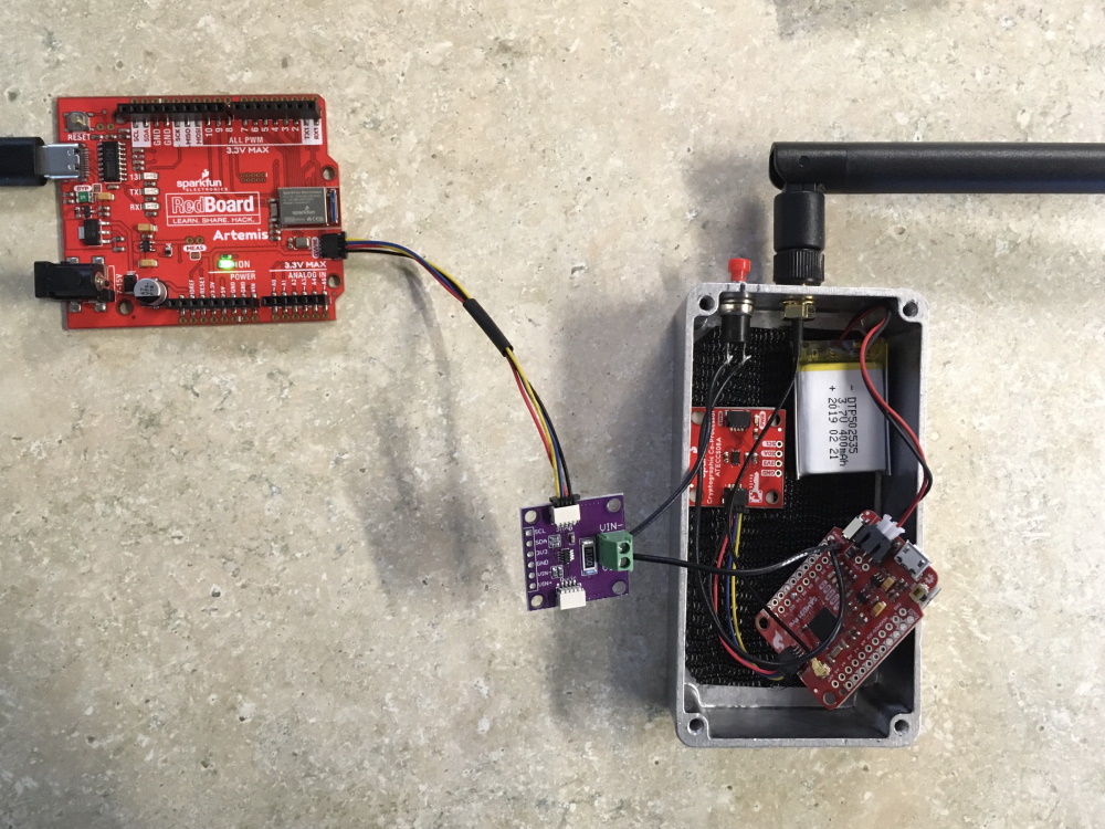
Now I wanted to consider how much power is actually being used during each attempt to open the garage door. I hooked up an SparkFun RedBoard Artemis and a Zio Current and Voltage Sensor - INA219 (Qwiic), and I had some data streaming in no time!
Here is what a complete cycle looked like on the serial plotter and monitor:
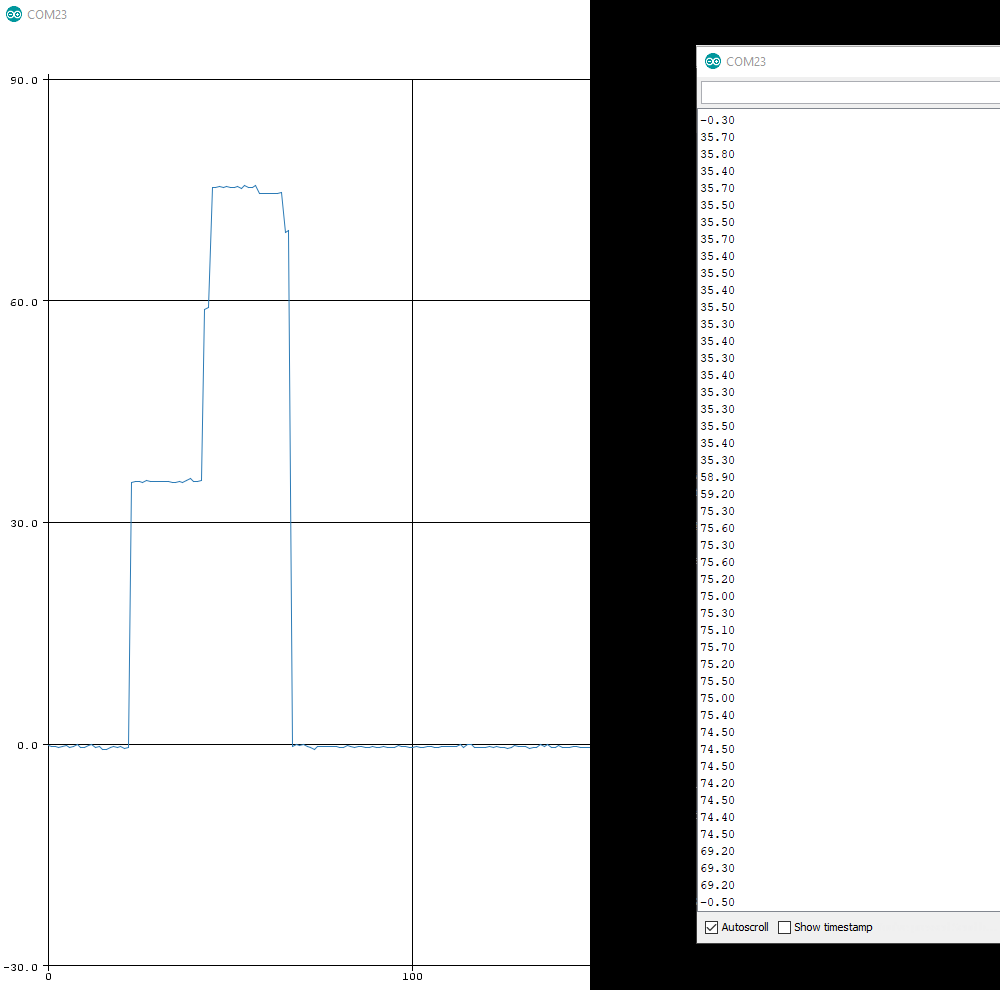
Each reading is precisely 100ms apart, so adding them all up I can see that it will use 0.065mAh per cycle.
21 readings (2100ms) at 36mA = 0.021mAh
1 reading (100ms) at 56mA = 0.002mAh
20 readings (2000ms) at 76mA = 0.042mAh
Total: 0.065mAh
Battery capacity is 400mAh
400mAh / 0.065mAh = 6,153
So according to my rough math, I think I can press this button 6153 times with this single battery. At 2 times a day, 300 days a year (600/year), that's 10 years. Even with capacity loss during storage in my car (let's say 10% each year), it'll still should last... let's see...
Year: capacity : -10% - yearly use for cycles (600 * 0.065 = ~40mAh)
Year 1 : 400 - 40 - 40 = 320
Year 2 : 320 - 32 - 40 = 248
Year 3 : 248 - 25 - 40 = 183
Year 4 : 183 - 18 - 40 = 125
Year 5 : 125 - 13 - 40 = 72
Year 6 : 72 - 7 - 40 = 25
Wahoo! Six years is pretty good. Now I just need to make sure it doesn't get squashed somewhere in my car.
Arduino Code
There are two separate sketches: one for the remote control and a second for the base transceiver. You can see both sketches in the project GitHub repository located here:
The code used in this project was kept fairly clean by using three Arduino Libraries:
- SparkFun_ATECCX08a_Arduino_Library
- SparkFun Qwiic Relay Arduino Library Github Repo
- Radiohead Arduino Library
For help with installing each necessary Arduino library, see the individual hookup guides for the Qwiic Relay and Cryptographic Co-processor. But you can also check out a more general tutorial on Arduino library installation here:
Installing an Arduino Library
January 11, 2013
Also, to use the SparkFun Pro RF, you will need to install the SAMD board packages. For more information on how to do that, you can take a look at this section of the Pro RF Hookup Guide. Now let's take a closer look at each individual sketch.
Remote Control Sketch
This sketch basically does everything inside its setup(). This is because, it will actually remain un-powered for most of its life. When I want to power it up and begin an entire attempt cycle, I will press the momentary button on the enclosure and this will supply power.
After setting up the RF module, the cryptographic co-processor and button, the most important thing to note is that it calls "attempt_cycle" at the very end of setup(). All the good stuff happens in there!
The attempt_cycle() function does essentially four things:
- Engages a cycle by sending "$$$".
- Receives 64-byte token.
- Creates the ECC signature.
- Sends Signature back to the base.
language:c
    /*
  Remote Control
  This sketch is used to create a cryptographically secure wireless controller to open you garage.
  The complete system uses SparkFun Pro RF modules, Cryptographic Co-processors, and the qwiic relay.
  Note, it also requires a base transceiver setup with separate sketch.

  See the complete tutorial here:
  https://learn.sparkfun.com/tutorials/secure-diy-garage-door-opener

  By: Pete Lewis
  SparkFun Electronics
  Date: January 13th, 2020
  License: This code is public domain but you can buy me a beer if you use this and we meet someday (Beerware license).

  Feel like supporting our work? Please buy a board from SparkFun!
  https://www.sparkfun.com/products/15573

  Some of this code is a modified version of the example provided by the Radio Head
  Library which can be found here:
  www.github.com/PaulStoffregen/RadioHeadd

  Some of this code is a modified version of the example provided by the SparkFun ATECCX08a
  Arduino Library which can be found here:
  https://github.com/sparkfun/SparkFun_ATECCX08a_Arduino_Library
*/

#include <SPI.h>

//Radio Head Library:
#include <RH_RF95.h>

// We need to provide the RFM95 module's chip select and interrupt pins to the
// rf95 instance below.On the SparkFun ProRF those pins are 12 and 6 respectively.
RH_RF95 rf95(12, 6);

int LED = 13; //Status LED is on pin 13

int packetCounter = 0; //Counts the number of packets sent
long timeSinceLastPacket = 0; //Tracks the time stamp of last packet received

// The broadcast frequency is set to 921.2, but the SADM21 ProRf operates
// anywhere in the range of 902-928MHz in the Americas.
// Europe operates in the frequencies 863-870, center frequency at 868MHz.
// This works but it is unknown how well the radio configures to this frequency:
//float frequency = 864.1;
float frequency = 921.2; //Broadcast frequency


//////////////crypto stuff

#include <SparkFun_ATECCX08a_Arduino_Library.h> //Click here to get the library: http://librarymanager/All#SparkFun_ATECCX08a
#include <Wire.h>

ATECCX08A atecc;

uint8_t token[32]; // time to live token, created randomly each authentication event


/////////////

byte buf[RH_RF95_MAX_MESSAGE_LEN];

void setup()
{
  pinMode(LED, OUTPUT);

  SerialUSB.begin(115200);
  // It may be difficult to read serial messages on startup. The following line
  // will wait for serial to be ready before continuing. Comment out if not needed.
  //while (!SerialUSB);
  SerialUSB.println("RFM Client!");

  //Initialize the Radio.
  if (rf95.init() == false) {
    SerialUSB.println("Radio Init Failed - Freezing");
    while (1);
  }
  else {
    //An LED inidicator to let us know radio initialization has completed.
    //SerialUSB.println("Transmitter up!");
    //digitalWrite(LED, HIGH);
    //delay(500);
    //digitalWrite(LED, LOW);
    //delay(500);
  }

  // Set frequency
  rf95.setFrequency(frequency);

  // The default transmitter power is 13dBm, using PA_BOOST.
  // If you are using RFM95/96/97/98 modules which uses the PA_BOOST transmitter pin, then
  // you can set transmitter powers from 5 to 23 dBm:
  // Transmitter power can range from 14-20dbm.
  rf95.setTxPower(14, false);

  pinMode(5, INPUT_PULLUP);

  Wire.begin();

  if (atecc.begin() == true)
  {
    SerialUSB.println("Successful wakeUp(). I2C connections are good.");
  }
  else
  {
    SerialUSB.println("Device not found. Check wiring.");
    while (1); // stall out forever
  }

  attempt_cycle();

}


void loop()
{

  if (digitalRead(5) == LOW)
  {
//    attempt_cycle();
  }
  delay(10); // button debounce
}


void printBuf64()
{
  SerialUSB.println();
  SerialUSB.println("uint8_t buf[64] = {");
  for (int i = 0; i < 32 ; i++)
  {
    SerialUSB.print("0x");
    if ((buf[i] >> 4) == 0) SerialUSB.print("0"); // print preceeding high nibble if it's zero
    SerialUSB.print(buf[i], HEX);
    if (i != 31) SerialUSB.print(", ");
    if ((31 - i) % 16 == 0) SerialUSB.println();
  }
  SerialUSB.println("};");
  SerialUSB.println();
}

void printToken()
{
  SerialUSB.println();
  SerialUSB.println("uint8_t token[32] = {");
  for (int i = 0; i < sizeof(token) ; i++)
  {
    SerialUSB.print("0x");
    if ((token[i] >> 4) == 0) SerialUSB.print("0"); // print preceeding high nibble if it's zero
    SerialUSB.print(token[i], HEX);
    if (i != 31) SerialUSB.print(", ");
    if ((31 - i) % 16 == 0) SerialUSB.println();
  }
  SerialUSB.println("};");
  SerialUSB.println();
}


// Note, in Example4_Alice we are printing the signature we JUST created,
// and it lives inside the library as a public array called "atecc.signature"
void printSignature()
{
  SerialUSB.println("uint8_t signature[64] = {");
  for (int i = 0; i < sizeof(atecc.signature) ; i++)
  {
    SerialUSB.print("0x");
    if ((atecc.signature[i] >> 4) == 0) SerialUSB.print("0"); // print preceeding high nibble if it's zero
    SerialUSB.print(atecc.signature[i], HEX);
    if (i != 63) SerialUSB.print(", ");
    if ((63 - i) % 16 == 0) SerialUSB.println();
  }
  SerialUSB.println("};");
  SerialUSB.println();
}

void attempt_cycle()
{
  SerialUSB.println("Sending message");

  //Send a message to the other radio
  uint8_t toSend[] = "$$$";
  //sprintf(toSend, "Hi, my counter is: %d", packetCounter++);
  rf95.send(toSend, sizeof(toSend));
  rf95.waitPacketSent();

  // Now wait for a reply

  byte len = sizeof(buf);

  if (rf95.waitAvailableTimeout(2000)) {
    // Should be a reply message for us now
    if (rf95.recv(buf, &len)) {
      SerialUSB.print("Got reply: ");
      printBuf64();
      for (int i = 0 ; i < 32 ; i++) token[i] = buf[i]; // read in token from buffer.
      printToken(); // nice debug to see what token we just sent. see function below

      boolean sigStat = false;
      sigStat = atecc.createSignature(token); // by default, this uses the private key securely stored and locked in slot 0.

      SerialUSB.print("sigStat: ");
      SerialUSB.println(sigStat);

      //printSignature();


      // Copy our signature from library array to local toSend array
      //for (int i = 0 ; i < 64 ; i++) toSend[i] = atecc.signature[i]; // store locally

      //Send signature to the other radio
      rf95.send(atecc.signature, sizeof(atecc.signature));
      rf95.waitPacketSent();
      SerialUSB.println("Sent signature");
      //SerialUSB.println((char*)buf);
      //SerialUSB.print(" RSSI: ");
      //SerialUSB.print(rf95.lastRssi(), DEC);
    }
    else {
      SerialUSB.println("Receive failed");
    }
  }
  else {
    SerialUSB.println("No reply, is the receiver running?");
  }
  delay(500);
}
Base Transceiver Sketch
This sketch is very similar to the first Example Sketch in our hookup guide for the Pro RF: Point to Point Radio Arduino Examples. In fact, that's were I started from. And then I added in the necessary libraries for the Cryptographic chip and the Qwiic relay. And then I stole some code from each of their initial examples. A whole lot of copy/paste going on. Isn't that convenient, Gromit!
Inside the main loop, the Base does the following:
- Listens to incoming messages.
- If it receives a "$$$", then create a new random token and send it to remote.
- Listens for a signature from remote.
- Receives 64-byte signature.
- Verifies signature.
- If valid, trigger relay to "close" for 500ms, emulating a button press.
- If success hasn't happened within 1 second, destroy token. This protects against repeater attacks.
Note, whenever the Base hears any message come in, it checks for the "$$$". This will tell it if the message is an request or a signature. If it doesn't see "$$$" then it pulls in the next 64 bytes and attempts to verify the signature.
language:c
/*
  Base Transceiver
  This sketch is used to create a cryptographically secure wireless controller to open you garage.
  The complete system uses SparkFun Pro RF modules, Cryptographic Co-processors, and the qwiic relay.
  Note, it also requires a remote control setup with separate sketch.

  See the complete tutorial here:
  https://learn.sparkfun.com/tutorials/secure-diy-garage-door-opener

  By: Pete Lewis
  SparkFun Electronics
  Date: January 13th, 2020
  License: This code is public domain but you can buy me a beer if you use this and we meet someday (Beerware license).

  Feel like supporting our work? Please buy a board from SparkFun!
  https://www.sparkfun.com/products/15573

  Some of this code is a modified version of the example provided by the Radio Head
  Library which can be found here:
  www.github.com/PaulStoffregen/RadioHeadd

  Some of this code is a modified version of the example provided by the SparkFun ATECCX08a
  Arduino Library which can be found here:
  https://github.com/sparkfun/SparkFun_ATECCX08a_Arduino_Library

  Some of the code is a modified version of the example provided by the SparkFun Qwiic
  Relay Arduino Library which can be found here:
  https://github.com/sparkfun/SparkFun_Qwiic_Relay_Arduino_Library
*/


#include <SPI.h>

//Radio Head Library:
#include <RH_RF95.h>

// We need to provide the RFM95 module's chip select and interrupt pins to the
// rf95 instance below.On the SparkFun ProRF those pins are 12 and 6 respectively.
RH_RF95 rf95(12, 6);

int LED = 13; //Status LED on pin 13

int successLED = 3; // green
int failLED = 4; // red
int statLED = 2; // blue

int packetCounter = 0; //Counts the number of packets sent
long timeSinceLastPacket = 0; //Tracks the time stamp of last packet received
// The broadcast frequency is set to 921.2, but the SADM21 ProRf operates
// anywhere in the range of 902-928MHz in the Americas.
// Europe operates in the frequencies 863-870, center frequency at
// 868MHz.This works but it is unknown how well the radio configures to this frequency:
//float frequency = 864.1;
float frequency = 921.2;

uint8_t buf[RH_RF95_MAX_MESSAGE_LEN];


////////////////relay

#include "SparkFun_Qwiic_Relay.h"

#define RELAY_ADDR 0x18 // Alternate address 0x19


Qwiic_Relay relay(RELAY_ADDR);

////////////////

/////////////////crypto

#include <SparkFun_ATECCX08a_Arduino_Library.h> //Click here to get the library: http://librarymanager/All#SparkFun_ATECCX08a
#include <Wire.h>

ATECCX08A atecc;

uint8_t token[32]; // time to live token, created randomly each authentication event

uint8_t signature[64]; // incoming signature from Alice

int headerCount = 0; // used to count incoming "$", when we reach 3 we know it's a good fresh new message.

// Alice's public key.
// Note, this will be unique to each co-processor, so your will be different.
// copy/paste Alice's true unique public key from her terminal printout in Example6_Challenge_Alice.

uint8_t AlicesPublicKey[64] = {
  0x38, 0xD6, 0xE5, 0x49, 0xAC, 0x57, 0x2D, 0x1F, 0xD0, 0x58, 0x0A, 0xE8, 0x59, 0xB8, 0xF8, 0x20,
  0x1E, 0x0A, 0x7E, 0x8D, 0x5B, 0x7D, 0xD9, 0x8A, 0x26, 0xAF, 0x88, 0x73, 0x6D, 0x8C, 0xB7, 0x2D,
  0x8D, 0x3A, 0xB9, 0x5F, 0x60, 0x9D, 0x3F, 0x49, 0x72, 0xF1, 0x44, 0x74, 0x82, 0x3F, 0x7B, 0xCF,
  0x1F, 0x18, 0xD3, 0xA4, 0xBF, 0x62, 0x15, 0xCC, 0xAF, 0xAD, 0x7E, 0x03, 0xD8, 0xE9, 0x93, 0x7E
};

void setup()
{
  pinMode(LED, OUTPUT);
  pinMode(successLED, OUTPUT);
  pinMode(failLED, OUTPUT);
  pinMode(statLED, OUTPUT);

  SerialUSB.begin(115200);
  // It may be difficult to read serial messages on startup. The following
  // line will wait for serial to be ready before continuing. Comment out if not needed.
  //while (!SerialUSB);
  SerialUSB.println("RFM Server!");

  //Initialize the Radio.
  if (rf95.init() == false) {
    SerialUSB.println("Radio Init Failed - Freezing");
    while (1);
  }
  else {
    // An LED indicator to let us know radio initialization has completed.
    SerialUSB.println("Receiver up!");
    digitalWrite(LED, HIGH);
    delay(500);
    digitalWrite(LED, LOW);
    delay(500);
  }

  rf95.setFrequency(frequency);

  // The default transmitter power is 13dBm, using PA_BOOST.
  // If you are using RFM95/96/97/98 modules which uses the PA_BOOST transmitter pin, then
  // you can set transmitter powers from 5 to 23 dBm:
  // rf95.setTxPower(14, false);


  Wire.begin();

  if (atecc.begin() == true)
  {
    SerialUSB.println("Successful wakeUp(). I2C connections are good.");
  }
  else
  {
    SerialUSB.println("Device not found. Check wiring.");
    while (1); // stall out forever
  }

  if (!relay.begin())
  {
    Serial.println("Check connections to Qwiic Relay.");
    while (1); // stall out forever
  }
  else
  {
    Serial.println("Qwiic Relay is ready to go.");
  }

}

void loop()
{
  if (rf95.available()) {
    // Should be a message for us now

    uint8_t len = sizeof(buf);

    if (rf95.recv(buf, &len)) {
      digitalWrite(LED, HIGH); //Turn on status LED
      timeSinceLastPacket = millis(); //Timestamp this packet

      SerialUSB.print("Got message: ");
      printBuf64();
      //SerialUSB.print(" RSSI: ");
      //SerialUSB.print(rf95.lastRssi(), DEC);
      SerialUSB.println();

      // if message from Alice is "$$$", Send a random token for her to sign.
      if (buf[0] == '$' && buf[1] == '$' && buf[2] == '$')
      {
        SerialUSB.println("Received $$$. Creating a new random TTL-token now...");

        // update library instance public variable.
        atecc.updateRandom32Bytes();

        uint8_t toSend[32];
        // copy from library public variable into our local variable
        for (int i = 0 ; i < 32 ; i++)
        {
          token[i] = atecc.random32Bytes[i]; // store locally
        }

        rf95.send(token, sizeof(token));
        rf95.waitPacketSent();
        SerialUSB.println("Sent token");
        digitalWrite(LED, LOW); //Turn off status LED
      }
      else // this means Alice just sent us a signature
      {
        SerialUSB.println("Received signature. Verifying now...");
        for (int i = 0 ; i < 64 ; i++) signature[i] = buf[i]; // read in signature from buffer.
        printSignature();
        // Let's verirfy!
        if (atecc.verifySignature(token, signature, AlicesPublicKey))
        {
          SerialUSB.println("Success! Signature Verified.");
          // Let's turn on the relay...
          relay.turnRelayOn();
          delay(1000);
          // Let's turn that relay off...
          relay.turnRelayOff();
          blinkStatus(successLED);
        }
        else
        {
          SerialUSB.println("Verification failure.");
          blinkStatus(failLED);
        }
      }

    }
    else
      SerialUSB.println("Recieve failed");
  }
  //Turn off status LED if we haven't received a packet after 1s
  if (millis() - timeSinceLastPacket > 1000) {
    digitalWrite(LED, LOW); //Turn off status LED
    timeSinceLastPacket = millis(); //Don't write LED but every 1s
    clearBuf();
    // destory token, to require a new cycle if this doesn't complete within 1 second
    for (int i = 0 ; i < 32 ; i++)
    {
      token[i] = 0x00;
    }
  }
}


void printSignature()
{
  SerialUSB.println("uint8_t signature[64] = {");
  for (int i = 0; i < sizeof(signature) ; i++)
  {
    SerialUSB.print("0x");
    if ((signature[i] >> 4) == 0) SerialUSB.print("0"); // print preceeding high nibble if it's zero
    SerialUSB.print(signature[i], HEX);
    if (i != 63) SerialUSB.print(", ");
    if ((63 - i) % 16 == 0) SerialUSB.println();
  }
  SerialUSB.println("};");
  SerialUSB.println();
}

void printBuf64()
{
  SerialUSB.println();
  SerialUSB.println("uint8_t buf[64] = {");
  for (int i = 0; i < 64 ; i++)
  {
    SerialUSB.print("0x");
    if ((buf[i] >> 4) == 0) SerialUSB.print("0"); // print preceeding high nibble if it's zero
    SerialUSB.print(buf[i], HEX);
    if (i != 63) SerialUSB.print(", ");
    if ((63 - i) % 16 == 0) SerialUSB.println();
  }
  SerialUSB.println("};");
  SerialUSB.println();
}

void clearBuf()
{
  for (int i = 0; i < 64 ; i++) buf[i] = 0x00;
}

void blinkStatus(int LED)
{
  digitalWrite(LED, HIGH);
  delay(2000);
  digitalWrite(LED, LOW);
  delay(500);
}
Resources & Going Further
Now that you've incorporated ECC authentication security into your garage door opener, you can add security to any future project they may need it. How about your internet-connected front door?
For more information, check out the resources below:
Project Source Code
Hookup Guides
- SAMD21 Pro RF Hookup Guide
- Cryptographic Co-Processor ATECC508A (Qwiic) Hookup Guide
- Qwiic Single Relay Hookup Guide
Arduino Libraries
- SparkFun_ATECCX08a_Arduino_Library
- SparkFun Qwiic Relay Arduino Library Github Repo
- Radiohead Arduino Library
Videos
Need inspiration? Check out some of the Qwiic or IoT related tutorials!