Serial Controlled Motor Driver Hookup Guide
 MTaylor
Terminology
This guide and related documentation uses a few terms with specific meanings. When User and Expansion are used, it is referring to the physical pins of the connection. When Controller and Peripheral are used, it matches the I2C behavior on the expansion port, and refers to the connected chain of SCMDs.
- User Port -- Connects the user's project to the controller SCMD and is unused on peripherals.
- Expansion Port -- Connects a single controller and up to 16 peripherals, and should never be connected to the user's project.
- Controller -- The SCMD that is connected to the user's project. Also, it is the I2C controller on the expansion port
- Peripheral -- A SCMD that is only connected to a controller SCMD by way of the expansion port.
Note: The config in and out pins of the expansion port may sometimes be connected to the user's project for error checking and mitigation purposes.
Motor Polarity -- The driver and this document often omit motor polarity. This is because polarity to spin direction is not standardized, and it is assumed the user will attach them backwards 50% of the time. Each motor channel is independently configurable for what is thought of as 'forward' spin by command. It is assumed that the user will first attach the motors, then decide which channels need to be inverted and issue inversion settings at boot time.
Expansion Bus I2C Pull-Ups -- All controller SCMDs should have at least one set of pull-ups enabled for their expansion bus, even if no peripherals are present! The board's default state is disabled because pull-up resistors should be applied thoughtfully per design, but it means a single controller without peripherals will un-intuitively require the jumper to be closed.
Motor Numbering -- The SCMD's silkscreen shows connections for motor 'A' and motor 'B' to prevent confusion within a programming environment where numbers are used to denote motors or drivers.
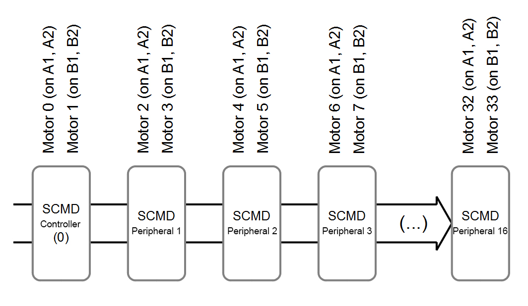
When somethings refers to a 'motor number', the following scheme is used. The motor attached to the controller at position 'A' will always be motor 0, and the 'B' position, motor 1. The first peripheral device attached will have motors 2, and 3, at positions 'A' and 'B' respectively. Peripheral 2 will have motors 4, and 5, and so on.
When a SCMD is designated as bridged mode, it loses whatever motor is attached to the 'B' position, and any information sent to control the 'A' position will control both outputs synchronously, such as inversion or drive strength.
This is not to be confused with 'driver number', which indicates which SCMD in the chain is being referenced.