Series and Parallel Circuits
 Pete-O
Series Circuits
Nodes and Current Flow
Before we get too deep into this, we need to mention what a node is. It's nothing fancy, just representation of an electrical junction between two or more components. When a circuit is modeled on a schematic, these nodes represent the wires between components.
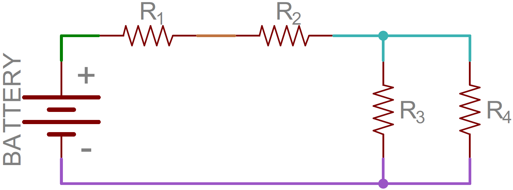
That's half the battle towards understanding the difference between series and parallel. We also need to understand how current flows through a circuit. Current flows from a high voltage to a lower voltage in a circuit. Some amount of current will flow through every path it can take to get to the point of lowest voltage (usually called ground). Using the above circuit as an example, here's how current would flow as it runs from the battery's positive terminal to the negative:
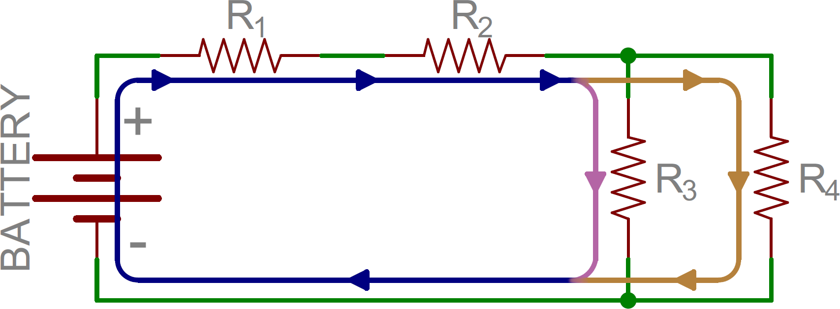
Notice that in some nodes (like between R1 and R2) the current is the same going in as at is coming out. At other nodes (specifically the three-way junction between R2, R3, and R4) the main (blue) current splits into two different ones. That's the key difference between series and parallel!
Series Circuits Defined
Two components are in series if they share a common node and if the same current flows through them. Here's an example circuit with three series resistors:
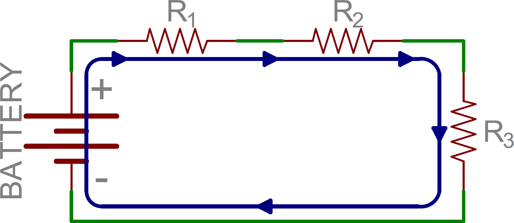
There's only one way for the current to flow in the above circuit. Starting from the positive terminal of the battery, current flow will first encounter R1. From there the current will flow straight to R2, then to R3, and finally back to the negative terminal of the battery. Note that there is only one path for current to follow. These components are in series.