Shift Registers
 JordanDee
Example
Hardware Hookup
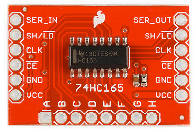
We will use the 74HC165 breakout board and an Arduino Uno to show how to do a parallel-in to serial-out for this example.
An 8-bit shift register needs 4 lines of a microcontroller. One for the Clock to time the data transfer, one to the enable the clock, one for loading/latching/shifting the bits, and one for the serial data transfer.
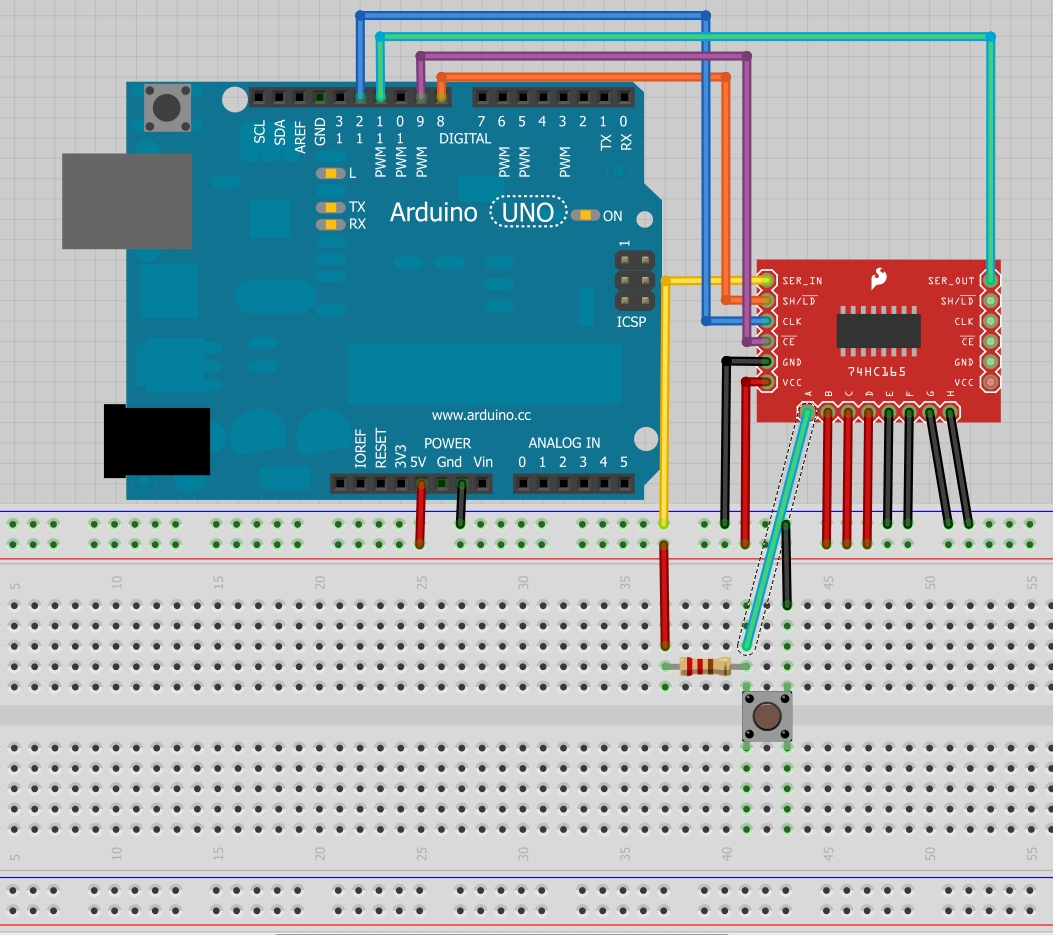
Connect clock (CLK) to pin 12 and clock enable (CE) to pin 9. The clock sets the frequency that bits are shifted while the clock enable line allows the clock signal to propagate through to the shifting circuitry.
Connect shift/load (SH/LD) to pin 8. A transition to low on the load pin tells the shift register to grab the current state of the 8 input pins(A-H). Pins A-H can be connected to some type of input like buttons, switches, or a digital transistor circuit. If you are testing them, it's recommended to just directly tie them to power or ground to make sure everything is working correctly. For the sake of this example, I'll connect one to a button with a pull up resistor and the rest to power or ground.
Connect the serial out (SER_OUT) to pin 11. This pin is where we receive the serial information from the shift register. Also, connect serial in (SER_IN) to ground. If you were chaining multiple shift registers together, serial in would be attached to the serial out of the last register. The first register in line would still have its serial in pin connected to ground while the last in the chain would have its serial out connected back to the microprocessor instead of another shift register.
Don't forget to connect power (2V-6V) and ground as well. With everything hooked up, let's take a look at the firmware.
Firmware
Here's a brief rundown of what the code does. It first initializes all the pins we connected to outputs with the exception of the pin we receive serial information on. We set the clock and shift pin to initial states (HIGH) as described by the datasheet. In order to read the state of the pins A-H, we need to tell the shift register to capture the state of the pins. We do this by pulling the load pin LOW briefly (5 microseconds). Once the pins are loaded, we make sure the rest of the pins are in the starting state as described by the datasheet and use the Arduino shiftIn function to pull all 8 A-H pin values into a byte called incoming. The values are printed out cleanly on the Serial Terminal. It then waits and repeats. If you're connecting pins like we did above, it should be easy to test if your hardware is working correctly.
Here's the code:
language:cpp
// HARDWARE CONNECTIONS
// Connect the following pins between your Arduino and the 74HC165 Breakout Board
// Connect pins A-H to 5V or GND or switches or whatever
const int data_pin = 11; // Connect Pin 11 to SER_OUT (serial data out)
const int shld_pin = 8; // Connect Pin 8 to SH/!LD (shift or active low load)
const int clk_pin = 12; // Connect Pin 12 to CLK (the clock that times the shifting)
const int ce_pin = 9; // Connect Pin 9 to !CE (clock enable, active low)

byte incoming; // Variable to store the 8 values loaded from the shift register

// The part that runs once
void setup()
{
  // Initialize serial to gain the power to obtain relevant information, 9600 baud
  Serial.begin(9600);

  // Initialize each digital pin to either output or input
  // We are commanding the shift register with each pin with the exception of the serial
  // data we get back on the data_pin line.
  pinMode(shld_pin, OUTPUT);
  pinMode(ce_pin, OUTPUT);
  pinMode(clk_pin, OUTPUT);
  pinMode(data_pin, INPUT);

  // Required initial states of these two pins according to the datasheet timing diagram
  digitalWrite(clk_pin, HIGH);
  digitalWrite(shld_pin, HIGH);

}

// The part that runs to infinity and beyond
void loop() {

  incoming = read_shift_regs(); // Read the shift register, it likes that

  // Print out the values being read from the shift register
  Serial.println("\nThe incoming values of the shift register are: ");
  Serial.print("ABCDEFGH : ");
  print_byte(incoming); // Print every 1 and 0 that correlates with A through H
  //Serial.println(incoming,BIN); // This way works too but leaves out the leading zeros

  delay(2000); // Wait for some arbitrary amount of time

}

// This code is intended to trigger the shift register to grab values from it's A-H inputs
byte read_shift_regs()
{
  byte the_shifted = 0;  // An 8 bit number to carry each bit value of A-H

  // Trigger loading the state of the A-H data lines into the shift register
  digitalWrite(shld_pin, LOW);
  delayMicroseconds(5); // Requires a delay here according to the datasheet timing diagram
  digitalWrite(shld_pin, HIGH);
  delayMicroseconds(5);

  // Required initial states of these two pins according to the datasheet timing diagram
  pinMode(clk_pin, OUTPUT);
  pinMode(data_pin, INPUT);
  digitalWrite(clk_pin, HIGH);
  digitalWrite(ce_pin, LOW); // Enable the clock

  // Get the A-H values
  the_shifted = shiftIn(data_pin, clk_pin, MSBFIRST);
  digitalWrite(ce_pin, HIGH); // Disable the clock

  return the_shifted;

}

// A function that prints all the 1's and 0's of a byte, so 8 bits +or- 2
void print_byte(byte val)
{
    byte i;
    for(byte i=0; i<=7; i++)
    {
      Serial.print(val >> i & 1, BIN); // Magic bit shift, if you care look up the <<, >>, and & operators
    }
    Serial.print("\n"); // Go to the next line, do not collect $200
}
Here's example output:
language:text
The incoming values of the shift register are:
ABCDEFGH : 11110000
Now, try connecting each input to buttons or adding another shift register into the mix. If you chain more together, you'll have to modify the code slightly by doing the loading once, then doing a shiftIn for each shift register you have before loading again.