SIK Experiment Guide for the Arduino 101/Genuino 101 Board
 D___Run___
 Experiment 1: Blinking an LED
Introduction
LEDs are small, powerful lights that are used in many different applications. To start off, we will work on blinking an LED, the Hello World of microcontrollers. That's right -- it's as simple as turning a light on and off. It might not seem like much, but establishing this important baseline will give you a solid foundation as we work toward more complex experiments.
Parts Needed
You will need the following parts:
- 1x Breadboard
- 1x Arduino 101 or Genuino 101 board
- 1x LED
- 1x 100Ω Resistor
- 3x Jumper Wires
Didn't Get the 101 SIK?
If you are conducting this experiment and didn't get the 101 SIK, we suggest using these parts:


You will also need either an Arduino 101 OR Genuino 101 board.


Suggested Reading
Before continuing with this experiment, we recommend you be familiar with the concepts in the following tutorial:
- Light-Emitting Diodes -- Learn more about LEDs!
Introducing the LED
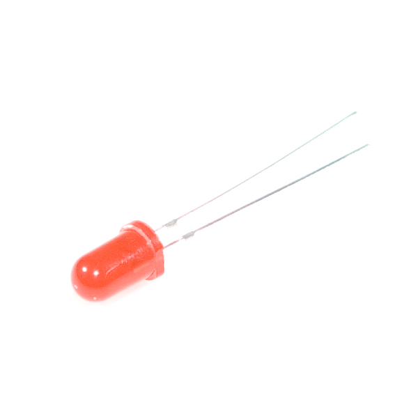
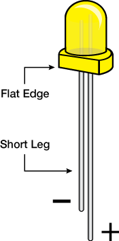
A Light-Emitting Diode (LED) will only let current through it in one direction. Think of an LED as a one-way street. When current flows through the LED, it lights up! When you are looking at the LED, you will notice that its legs are different lengths. The long leg, the "anode," is where current enters the LED. This pin should always be connected to the current source. The shorter leg, the "cathode," is the current’s exit. The short leg should always be connected to a pathway to ground.
LEDs are finicky when it comes to how much current you apply to them. Too much current can lead to a burnt-out LED. To restrict the amount of current that passes through the LED, we use a resistor in line with the power source and the LED's long leg; this is called a current-limiting resistor. With the 101 board, you should use a 100 Ohm resistor. We have included a baggy of them in the kit just for this reason!
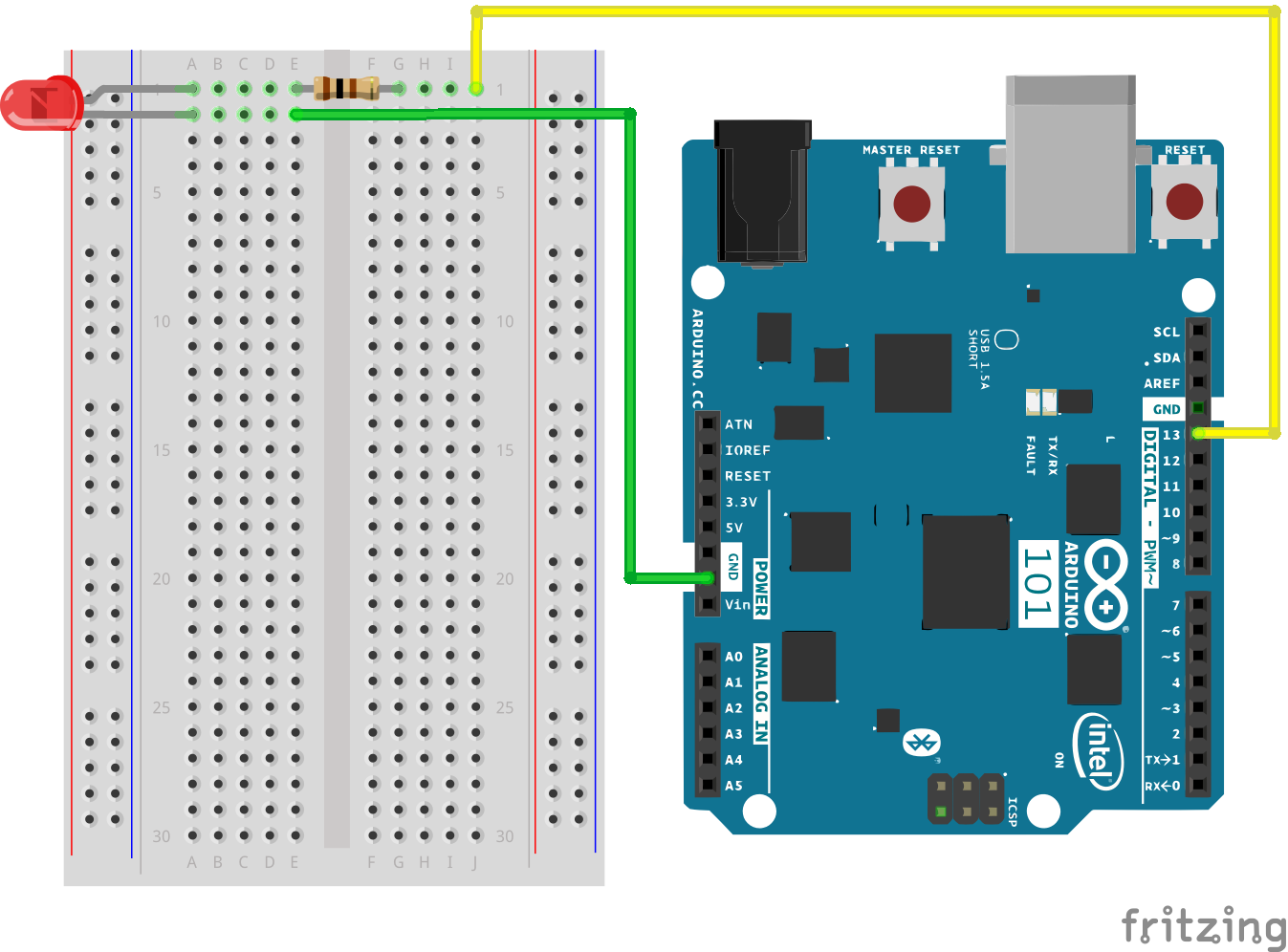
Hardware Hookup
Ready to start hooking everything up? Check out the wiring diagram and hookup table below to see how everything is connected.
| Polarized Components | Pay special attention to the component’s markings indicating how to place it on the breadboard. Polarized components can only be connected to a circuit in one direction. Polarized components are highlighted with a yellow warning triangle in the table below. |
**Please note: Pay close attention to the LED. The negative side of the LED is the short leg, marked with a flat edge. **
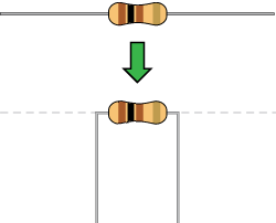
Components like resistors need to have their legs bent into 90° angles in order to correctly fit the breadboard sockets. You can also cut the legs shorter to make them easier to work with on the breadboard.
Wiring Diagram for the Experiment
Open Your First Sketch
Open the Arduino IDE software on your computer. Coding in the Arduino language will control your circuit. Open the code for Circuit 1 by accessing the “101 SIK Guide Code” you downloaded and placed into your “Examples” folder earlier.
To open the code go to: File > Examples > 101 SIK Guide Code > Circuit_01
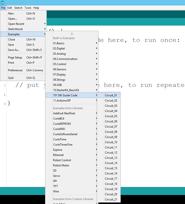
You can also copy and paste the following code into the Arduino IDE. Hit upload, and see what happens!
language:cpp
/*
SparkFun Inventor's Kit for the Arduino / Genuino 101
Example sketch 01

BLINKING AN LED

Turn an LED on for one second, off for one second,
and repeat forever.

This sketch was written by SparkFun Electronics,
with lots of help from the Arduino community.
This code is completely free for any use.
Visit http://learn.sparkfun.com/products/2 for SIK information.
Visit http://www.arduino.cc to learn about Arduino.
*/


//The setup function runs once upon your Arduino being powered or once upload is          //complete.

void setup()
{
  //set pin 13 to OUTPUT
  pinMode(13, OUTPUT);
}

//The loop function runs from the top down and repeats itself until you upload new        //code or power down your Arduino
void loop()
{
  //Turn pin 13 HIGH (ON).
  digitalWrite(13, HIGH);

  //wait 1000 milliseconds (1 second)
  delay(1000);

  //Turn pin 13, LOW (OFF)
  digitalWrite(13, LOW);

  //wait 1000 milliseconds
  delay(1000);
}
Code to Note
pinMode(13, OUTPUT);
Before you can use one of the 101's pins, you need to tell the board whether it is an INPUT or OUTPUT. We use a built-in "function" called pinMode() to do this.
digitalWrite(13, HIGH);
When you're using a pin as an OUTPUT, you can command it to be HIGH (output 3.3 volts), or LOW (output 0 volts).
What You Should See
You should see your LED blink on and off. If it doesn't, make sure you have assembled the circuit correctly and verified and uploaded the code to your board, or see the Troubleshooting section.

Troubleshooting
Program Not Uploading
This happens sometimes; the most likely cause is a confused serial port. You can change this in Tools > Serial Port >
Also, if you get a Timeout error or the IDE could not find your 101 board, try pressing the Master Reset button on the 101, wait around 10 seconds and try re-uploading your sketch.