SIK Experiment Guide for the Arduino 101/Genuino 101 Board
 D___Run___
 Experiment 10: Driving a Servo Motor
Introduction
This experiment is your introduction to the servo motor, which is a smart motor that you can tell to rotate to a specific angular location. You will program it to rotate to a series of locations, then sweep across its full range of motion, and then repeat.
Parts Needed
You will need the following parts:
- 1x Breadboard
- 1x Arduino 101 or Genuino 101 board
- 1x Servo
- 3x Jumper Wires
Didn't Get the SIK?
If you are conducting this experiment and didn't get the SIK, we suggest using these parts:


You will also need either an Arduino 101 OR Genuino 101 board.


Suggested Reading
Before continuing with this experiment, we recommend you be familiar with the concepts in the following tutorial:
Introducing the Servo Motor

Unlike the action of most motors that continuously rotate, a servo motor can rotate to and hold a specific angle until it is told to rotate to a different angle. You can control the angle of the servo by sending it a PWM pulse train; the PWM signal is mapped to a specific angle from 0 to 180 degrees.
Inside of the servo there is a gearbox connected to a motor that drives the shaft. There is also a potentiometer that gives feedback on the rotational position of the servo, which is then compared to the incoming PWM signal. The servo adjusts accordingly to match the two signals.
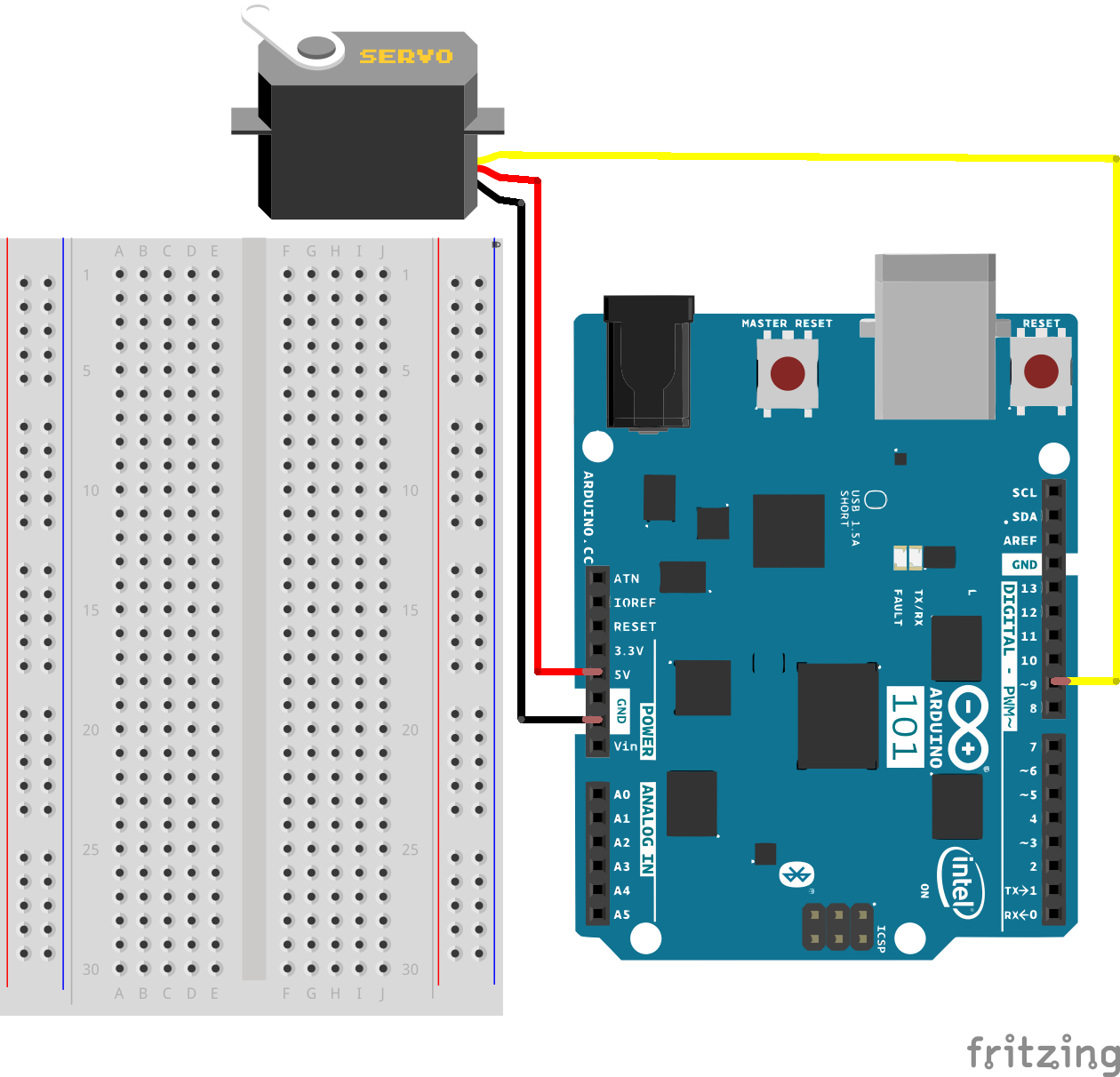
In this experiment, the servo is powered through 5V on the red wire, ground on the black wire, and the white wire is connected to a digital GPIO pin on which you can use PWM (9, 6, 5, 3 on the 101 board).
Hardware Hookup
Ready to start hooking everything up? Check out the wiring diagram below to see how everything is connected.
| Polarized Components | Pay special attention to the component’s markings indicating how to place it on the breadboard. Polarized components can only be connected to a circuit in one direction. |
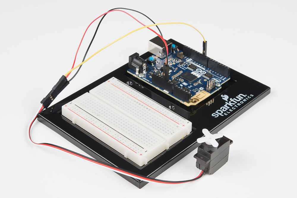
Connect 3x jumper wires to the female 3-pin header on the servo. This will make it easier to breadboard the servo.
Wiring Diagram for the Experiment
Open the Sketch
Open the Arduino IDE software on your computer. Coding in the Arduino language will control your circuit. Open the code for Circuit 10 by accessing the “101 SIK Guide Code” you downloaded and placed into your “Examples” folder earlier.
To open the code go to: File > Examples > 101 SIK Guide Code > Circuit_10
You can also copy and paste the following code into the Arduino IDE. Hit upload, and see what happens!
language:cpp
/*
SparkFun Inventor's Kit
Example sketch 10

SINGLE SERVO

  Sweep a servo back and forth through its full range of motion.

This sketch was written by SparkFun Electronics,
with lots of help from the Arduino community.
This code is completely free for any use.
Visit http://learn.sparkfun.com/products/2 for SIK information.
Visit http://www.arduino.cc to learn more about Arduino.
*/

//include the servo library
#include <Servo.h>

//create a servo object called servo1
Servo servo1;


void setup()
{
  //attach servo1 to pin 9 on the Arduino 101
  servo1.attach(9);
}


void loop()
{
  //create a local variable to store the servo's position.
  int position;

  // To control a servo, you give it the angle you'd like it
  // to turn to. Servos cannot turn a full 360 degrees, but you
  // can tell it to move anywhere between 0 and 180 degrees.

  // Change position at full speed:

  // Tell servo to go to 90 degrees
  servo1.write(90);

  // Pause to get it time to move
  delay(1000);

  // Tell servo to go to 180 degrees
  servo1.write(180);

  // Pause to get it time to move
  delay(1000);

  // Tell servo to go to 0 degrees
  servo1.write(0);

  // Pause to get it time to move
  delay(1000);


  // Tell servo to go to 180 degrees, stepping by two degrees
  for(position = 0; position < 180; position += 2)
  {
  // Move to next position
    servo1.write(position);
     // Short pause to allow it to move
    delay(20);
  }

  // Tell servo to go to 0 degrees, stepping by one degree
  for(position = 180; position >= 0; position -= 1)
  {
    // Move to next position
    servo1.write(position);
    // Short pause to allow it to move
    delay(20);
  }
}
Code to Note
#include <Servo.h>
#include is a special "preprocessor" command that inserts a library (or any other file) into your sketch. You can type this command yourself, or choose an installed library from the "sketch / import library" menu.
Servo servo1;
When you use a library, you create what is called an object of that library and name it. This object is a Servo library object, and it is named servo1. If you were using multiple servos you would name each one in this way.
servo1.attach(9);
The servo library adds new commands that let you control a servo. To prepare the Arduino to control a servo, you must first create a Servo "object" for each servo (here we've named it "servo1"), and then "attach" it to a digital pin (here we're using pin 9). Think of this as the servo's way of calling a pinMode() function.
servo1.write(180);
The servos in this kit don't spin all the way around, but they can be commanded to move to a specific position. We use the servo library's write() command to move a servo to a specified number of degrees (0 to 180). Remember that the servo requires time to move, so give it a short delay() if necessary.
What You Should See
You should see your servo motor move to various locations at several speeds. If the motor doesn't move, check your connections and make sure you have verified and uploaded the code, or see the Troubleshooting section.
Troubleshooting
Servo Not Twisting
Even with colored wires it is still shockingly easy to plug a servo in backward. This might be the case.
Still Not Working
A mistake we made a time or two was simply forgetting to connect the power (red and black wires) to 5 volts and ground (GND).
Fits and Starts
If the servo begins moving, then twitches, and there's a flashing light on your 101, the power supply you are using is not quite up to the challenge. Using a wall adapter instead of USB should solve this problem.