SIK Experiment Guide for the Arduino 101/Genuino 101 Board
 D___Run___
 Experiment 11: Using a Transistor
Introduction
In the previous experiment, you got to work with a servo motor. Now, we are going to tackle spinning a motor. This requires the use of a transistor, which can switch a larger amount of current than the 101 board can. You will use the transistor to turn a motor on and off -- that's right, a blinking motor!
Parts Needed
You will need the following parts:
- 1x Breadboard
- 1x Arduino 101 or Genuino 101 board
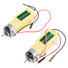
- 1x 48:1 Ratio Gearmotor
- 1x 100Ω Resistor
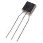
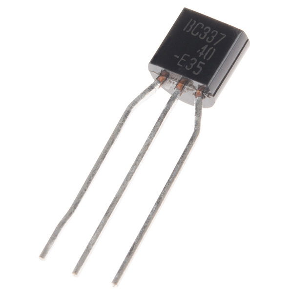
- 1x NPN Transistor
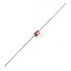
- 1x Diode 1N4148
- 7x Jumper Wires
Didn't Get the SIK?
If you are conducting this experiment and didn't get the SIK, we suggest using these parts:


You will also need either an Arduino 101 OR Genuino 101 board.


Suggested Reading
Before continuing with this experiment, we recommend you be familiar with the concepts in the following tutorials:
Introducing the Transistor
The transistor can be described as a small electronic switch. It allows you to control larger current loads with a smaller current without the risk of burning up sensitive components. A transistor has three pins: a collector, an emitter, and a base. Current can only flow into the transistor in one direction -- through the collector and out the emitter. To control the flow of the current, you apply a small current to the base. This small current can either be digital (on or off) or analog (through using PWM and the analogWrite() function). The larger current will be mirrored from what the smaller current is doing.
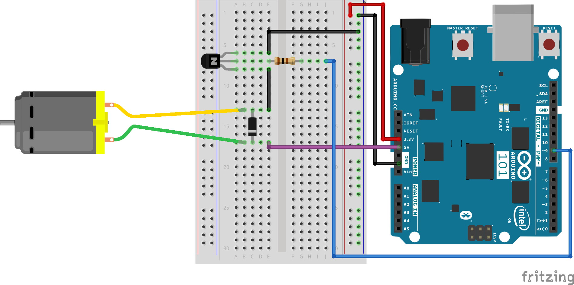
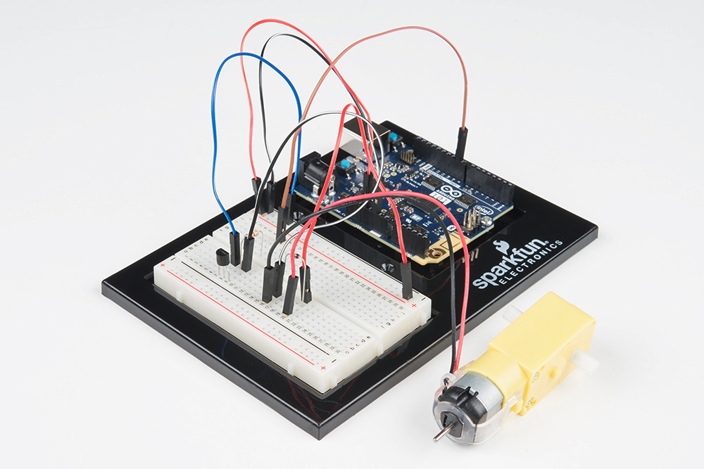
Hardware Hookup
Ready to start hooking everything up? Check out the wiring diagram below to see how everything is connected.
| Polarized Components | Pay special attention to the component’s markings indicating how to place it on the breadboard. Polarized components can only be connected to a circuit in one direction. |
Please note: When you’re building the circuit be careful not to mix up the transistor and the temperature sensor; they’re almost identical. Look for “P2N2222A” on the body of the transistor.
Wiring Diagram for the Experiment
What is a Flyback Diode?
When the spinning motor is suddenly turned off, the magnetic field inside it collapses, generating a voltage spike. This can damage the transistor. To prevent this, we use a "flyback diode," which diverts the voltage spike "around" the transistor. Connect the side of the diode with the band (cathode) to 5V. Connect the other side of the diode (anode) to the black wire on the motor.
Open the Sketch
Open the Arduino IDE software on your computer. Coding in the Arduino language will control your circuit. Open the code for Circuit 11 by accessing the “101 SIK Guide Code” you downloaded and placed into your “Examples” folder earlier.
To open the code go to: File > Examples >101 SIK Guide Code > Circuit_11
You can also copy and paste the following code into the Arduino IDE. Hit upload, and see what happens!
language:cpp
/*
SparkFun Inventor's Kit
Example sketch 11

SPINNING A MOTOR

  Use a transistor to spin a motor at different speeds.

This sketch was written by SparkFun Electronics,
with lots of help from the Arduino community.
This code is completely free for any use.
Visit http://learn.sparkfun.com/products/2 for SIK information.
Visit http://www.arduino.cc to learn more about Arduino.
*/

// constant pin for the transistor connected to the motor
const int motorPin = 9;


void setup()
{
  //set motorPin as OUTPUT
  pinMode(motorPin, OUTPUT);
}


void loop()
{
  // Here we've used comments to disable some of the examples.
  // To try different things, uncomment one of the following lines
  // and comment the other ones. See the functions below to learn
  // what they do and how they work.

   motorOnThenOff();
  // motorOnThenOffWithSpeed();
  // motorAcceleration();
}


// This function turns the motor on and off like the blinking LED.
// Try different values to affect the timing.
void motorOnThenOff()
{
  // milliseconds to turn the motor on
  int onTime = 3000;
  // milliseconds to turn the motor off
  int offTime = 3000;

  // turn the motor on (full speed)
  digitalWrite(motorPin, HIGH);
  // delay for onTime milliseconds
  delay(onTime);
  // turn the motor off
  digitalWrite(motorPin, LOW);
  // delay for offTime milliseconds
  delay(offTime);
}


// This function alternates between two speeds.
// Try different values to affect the timing and speed.
void motorOnThenOffWithSpeed()
{
  // between 0 (stopped) and 255 (full speed)
  int Speed1 = 200;
   // milliseconds for speed 1
  int Time1 = 3000;

  // between 0 (stopped) and 255 (full speed)
  int Speed2 = 50;
  // milliseconds to turn the motor off
  int Time2 = 3000;

  // turns the motor On
  analogWrite(motorPin, Speed1);
  // delay for onTime milliseconds
  delay(Time1);
  // turns the motor Off
  analogWrite(motorPin, Speed2);
  // delay for offTime milliseconds
  delay(Time2);
}


// This function slowly accelerates the motor to full speed,
// then back down to zero.
void motorAcceleration()
{
  // milliseconds between each speed step
  int speed;
  int delayTime = 20;

  // accelerate the motor
  for(speed = 0; speed <= 255; speed++)
  {
    // set the new speed
    analogWrite(motorPin,speed);
    // delay between speed steps
    delay(delayTime);
  }

  // decelerate the motor
  for(speed = 255; speed >= 0; speed--)
  {
    // set the new speed
    analogWrite(motorPin,speed);
    // delay between speed steps
    delay(delayTime);
  }
}
What You Should See
The DC Motor should spin if you have assembled the circuit’s components correctly, and also verified/uploaded the correct code. If your circuit is not working, check the Troubleshooting section.
Troubleshooting
Motor Not Spinning
If you sourced your own transistor, double check with the data sheet that the pinout is compatible with the transistor you are using (many are reversed).
Still No Luck
If you sourced your own motor, double check that it will work with 5 volts and that it does not draw too much power.
Still Not Working
Sometimes the Arduino will disconnect from the computer. Try unplugging and then replugging it into your USB port.