SIK Experiment Guide for the Arduino 101/Genuino 101 Board
 D___Run___
 Experiment 12: Using the Motor Driver
Introduction
In the previous experiment you controlled a motor. But, it only spun in one direction. How could you make it spin in both directions? With the SparkFun Motor Driver! In this experiment you will use the motor driver to control the motor's direction and speed.
Parts Needed
You will need the following parts:
- 1x Breadboard
- 1x Arduino 101 or Genuino 101 board
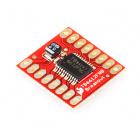
- 1x SparkFun Motor Driver Board
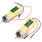
- 1x 48:1 Geared Motor
- 12x Jumper Wires
Didn't Get the SIK?
If you are conducting this experiment and didn't get the SIK, we suggest using these parts:


You will also need either an Arduino 101 OR Genuino 101 board.


Introducing the SparkFun Motor Driver

The SparkFun Motor Driver is a small circuit board that has all of the circuitry on it to make controlling motors easier. At the heart of the driver board is an H-Bridge, which allows you to control both the direction and the amount of an electrical current. You can think of it as a smart transistor that allows you to change the direction of the current.
To switch the direction of the current, you use two pins to toggle pins on the board either HIGH or LOW. If the two direction pins are both HIGH or LOW at the same time, that causes the board to brake the motors. If one pin is HIGH and the other is LOW, the motor spins in one direction. If you flip-flop the states, the motor spins in the opposite direction. This board also has a power-saving mode that uses a standby pin. To use the driver board, you pull the standby pin HIGH. If you are not using the board and want to conserve power, you can push the pin LOW, and the motors won’t run.
You can control up to two motors with a single driver board. The pin names are printed on the bottom of the controller board.
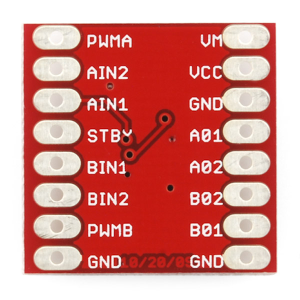
| PWMA | PWM signal for controlling the speed of motor A |
| AIN2 | Direction pin 2 for motor A |
| AIN1 | Direction pin 1 for motor A |
| STBY | Standby HIGH for board on, LOW for board off |
| BIN1 | Direction pin for motor B |
| BIN2 | Direction pin 2 for motor B |
| PWMB | PWM signal for controlling the speed of motor B |
| GND | Ground |
| VM | Motor power source 5V to 14V |
| VCC | Chip voltage (3.3V) |
| GND | Ground |
| A01 | Motor A connection |
| A02 | Motor A connection |
| B02 | Motor B Connection |
| B01 | Motor B Connection |
| GND | Ground |
Note: All ground pins need to be connected to ground, and the STBY pin cannot be floating, or not connected to ground or 3.3V. In this experiment, we hardwired it to 3.3V.
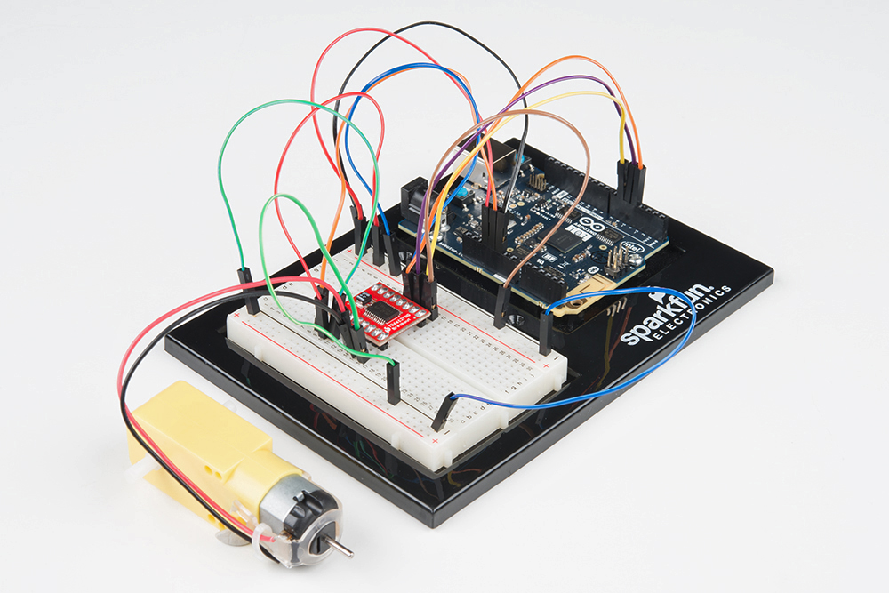
Hardware Hookup
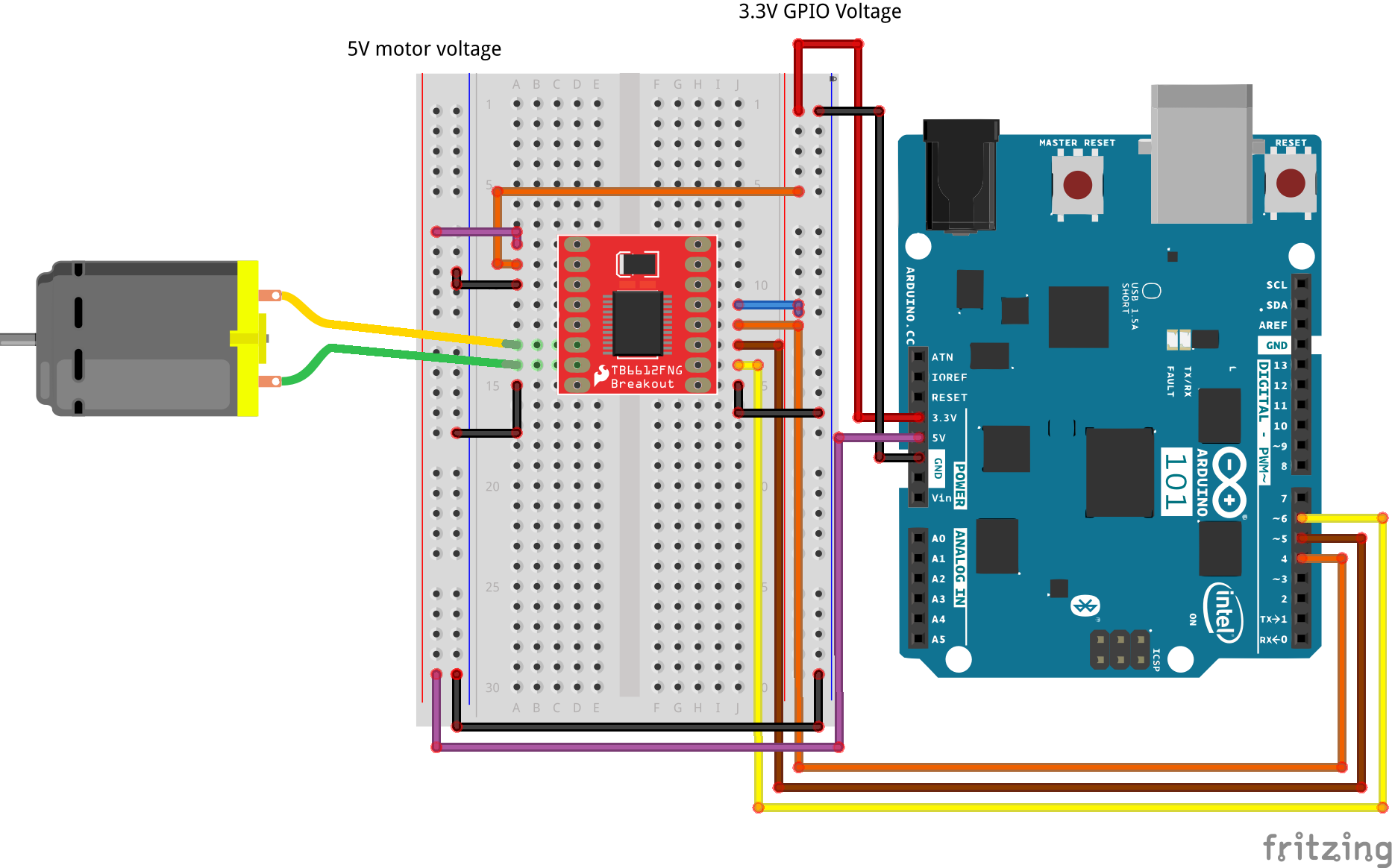
Ready to start hooking everything up? Check out the wiring diagram below to see how everything is connected.
| Polarized Components | Pay special attention to the component’s markings indicating how to place it on the breadboard. Polarized components can only be connected to a circuit in one direction. |
**Note: We hardwire or connect the standby pin directly to 3.3V. If you want to be able to enable/disable the motor controller in its entirety, you can connect it to a digital GPIO pin and toggle it using a digitalWrite(). **
Wiring Diagram for the Experiment
Open the Sketch
Open the Arduino IDE software on your computer. Coding in the Arduino language will control your circuit. Open the code for Circuit 12 by accessing the “101 SIK Guide Code” you downloaded and placed into your “Examples” folder earlier.
To open the code go to: File > Examples > 101 SIK Guide Code > Circuit_12
You can also copy and paste the following code into the Arduino IDE. Hit upload, and see what happens!
language:cpp
/*
SparkFun Inventor's Kit for Arduino
Example sketch 12

SparkFun Motor Driver

Use the SparkFun Motor Driver to control the speed and direction of a motor

This sketch was written by SparkFun Electronics,
with lots of help from the Arduino community.
This code is completely free for any use.
Visit http://learn.sparkfun.com/products/2 for SIK information.
Visit http://www.arduino.cc to learn more about Arduino.
*/

//define the two direction logic pins and the speed / PWM pin
const int DIR_A = 5;
const int DIR_B = 4;
const int PWM = 6;

void setup()
{
//set all pins as output
pinMode(DIR_A, OUTPUT);
pinMode(DIR_B, OUTPUT);
pinMode(PWM, OUTPUT);
}

void loop()
{
 //drive forward at full speed by pulling DIR_A High
 //and DIR_B low, while writing a full 255 to PWM to
 //control speed
 digitalWrite(DIR_A, HIGH);
 digitalWrite(DIR_B, LOW);
 analogWrite(PWM, 255);

 //wait 1 second
 delay(1000);

 //Brake the motor by pulling both direction pins to
 //the same state (in this case LOW). PWM doesn't matter
 //in a brake situation, but set as 0.
 digitalWrite(DIR_A, LOW);
 digitalWrite(DIR_B, LOW);
 analogWrite(PWM, 0);

 //wait 1 second
 delay(1000);

 //change direction to reverse by flipping the states
 //of the direction pins from their forward state
 digitalWrite(DIR_A, LOW);
 digitalWrite(DIR_B, HIGH);
 analogWrite(PWM, 150);

 //wait 1 second
 delay(1000);

 //Brake again
 digitalWrite(DIR_A, LOW);
 digitalWrite(DIR_B, LOW);
 analogWrite(PWM, 0);

 //wait 1 second
 delay(1000);
 }
Code to Note
 language:cpp
 digitalWrite(DIR_A, HIGH);
 digitalWrite(DIR_B, LOW);
 analogWrite(PWM, 255);
The Motor Driver uses a control logic that works by pulling certain pins HIGH or LOW (pins 4 and 5 in this case) to change the direction of the motor's rotation and then send a PWM signal to pin 6 to control the speed. This chunk of code runs to motor in one direction at full speed.
language:cpp
digitalWrite(DIR_A, LOW);
digitalWrite(DIR_B, HIGH);
analogWrite(PWM, 150);
This chunk of code is similar, but changes the direction by flipping the direction pin's state and setting the PWM pin at a slower speed.
language:cpp
digitalWrite(DIR_A, LOW);
digitalWrite(DIR_B, LOW);
analogWrite(PWM, 0);
This final chunk of code demonstrates the logic for stopping or "braking" the motor by pulling both direction pins to the same state. In this case we used LOW, but both set to HIGH would produce the same results. In a brake, the PWM level doesn't matter. We set it to 0 as more of a formality than anything. If not, see the Troubleshooting section below.
What You Should See
You should see the motor spin in one direction at full speed for a second, then brake for a second, reverse direction and run at 150 PWM speed for a second, brake, and then repeat.
Troubleshooting
Motor not Spinning
Make sure that you have the enable pin as well as the logic and PWM pins wired correctly. It's easy to make a wiring error, as the names of the pins of the board are on the bottom.
Double check that you have wired the standby pin to 3.3V! Without it, the IC is in standby mode.
Motor Spinning in Only One Direction
Double check your code. You may not have inverted the logic pin's state to reverse the motor.