SIK Experiment Guide for the Arduino 101/Genuino 101 Board
 D___Run___
 Experiment 16: Using a Shift Register
Introduction
Now we are going to step into the world of raw ICs (integrated circuits). In this experiment, you’ll learn all about using a shift register. The shift register will give your 101 board an additional eight outputs, using only three pins on your board. For this experiment, you’ll practice by using the shift register to control eight LEDs. That's right -- two more LEDs than Experiment 4!
Parts Needed
You will need the following parts:
- 1x Breadboard
- 1x Arduino 101 or Genuino 101 board
- 8x LEDs
- 8x 330Ω Resistors
- 1x Shift Register 8-Bit - 74HC595
- 19x Jumper Wires
Didn't Get the SIK?
If you are conducting this experiment and didn't get the SIK, we suggest using these parts:


You will also need either an Arduino 101 OR Genuino 101 board.


Suggested Reading
Before continuing with this experiment, we recommend you be familiar with the concepts in the following tutorials:
Introducing the Shift Register
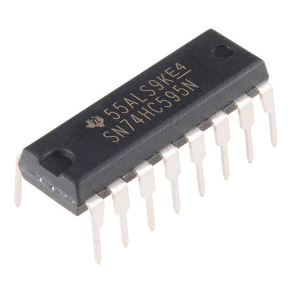
The shift register is an Integrated Circuit (IC). ICs are tiny, plastic-sealed packages of popular and often used circuits. ICs act as single components that perform a specific job function and simplify what used to be time- and space-consuming circuit design.
The shift register, in essence, allows you to control up to eight outputs while only using three pins on your 101 board. It enables you to control more outputs with fewer pins compared to Experiment 4, where you used six pins for six individual outputs.
Think of it this way: the data going into the shift register is like a train of eight different train cars. If a car is full of cargo, the data it represents is a 1. If the train car is empty, the data it represents is a 0. When the whole train has entered the shift register, it gets broken up, and each car gets placed on its own track. These tracks can be translated to the eight output pins of the shift register. If the car is full (1) the pin that it is on is pulled HIGH; if the car is empty (0) the pin is pulled LOW. If you constantly send train after train into the shift register, you can animate LEDs or control something like a 7-segment display to count down or even a whole lot of motors turning at different times. All of this happens just by sending the shift register trains with different patterns of 1s and 0s.
To learn more about trains shift registers, check out our Shift Register Tutorial.
Hardware Hookup
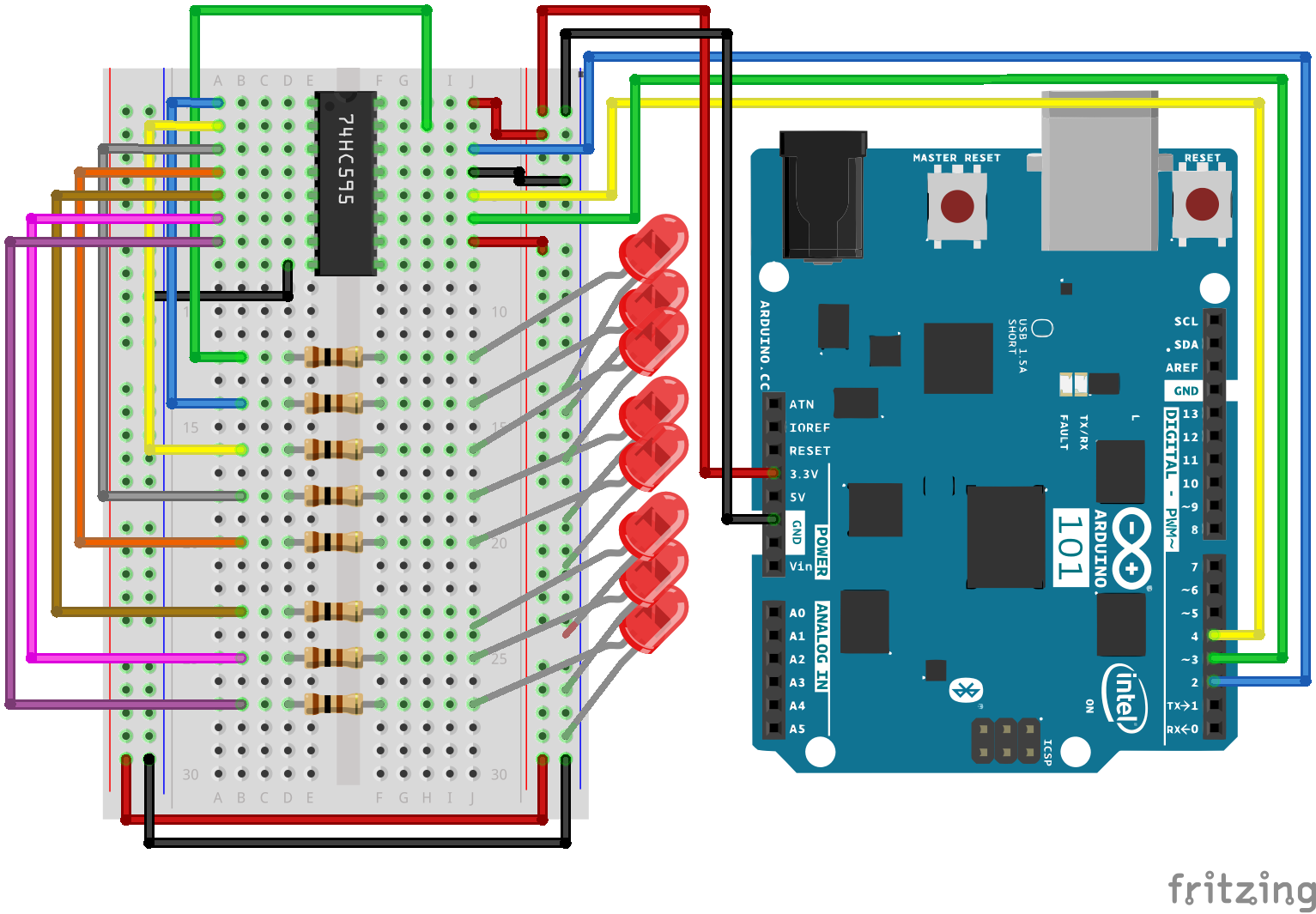
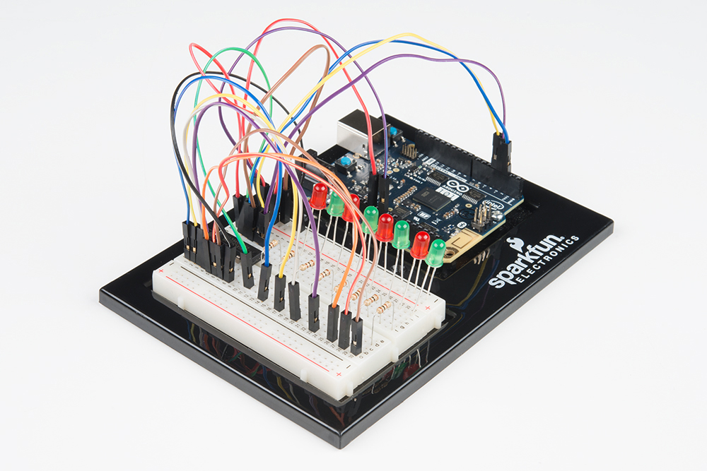
Ready to start hooking everything up? Check out the wiring diagram below to see how everything is connected.
| Polarized Components | Pay special attention to the component’s markings indicating how to place it on the breadboard. Polarized components can only be connected to a circuit in one direction. |
Wiring Diagram for the Experiment
Open the Sketch
Open the Arduino IDE software on your computer. Coding in the Arduino language will control your circuit. Open the code for Circuit 16 by accessing the “101 SIK Guide Code” you downloaded and placed into your “Examples” folder earlier.
To open the code go to: File > Examples >101 SIK Guide Code > Circuit_16
You can also copy and paste the following code into the Arduino IDE. Hit upload, and see what happens!
language:cpp
/*
SparkFun Inventor's Kit
Example sketch 16

SHIFT REGISTER

  Use a shift register to turn three pins into eight (or more!)
  outputs

This sketch was written by SparkFun Electronics,
with lots of help from the Arduino community.
This code is completely free for any use.
Visit http://learn.sparkfun.com/products/2 for SIK information.
Visit http://www.arduino.cc to learn more about Arduino.
*/


// Pin definitions:
// The 74HC595 uses a type of serial connection called SPI
// (Serial Peripheral Interface) that requires three pins:

int datapin = 2;
int clockpin = 3;
int latchpin = 4;

// We'll also declare a global variable for the data we're
// sending to the shift register:

byte data = 0;


void setup()
{
  // Set the three SPI pins to be outputs:

  pinMode(datapin, OUTPUT);
  pinMode(clockpin, OUTPUT);
  pinMode(latchpin, OUTPUT);
}


void loop()
{
  // We're going to use the same functions we played with back
  // in circuit 04, "Multiple LEDs," we've just replaced
  // digitalWrite() with a new function called shiftWrite()
  // (see below). We also have a new function that demonstrates
  // binary counting.

  // To try the different functions below, uncomment the one
  // you want to run, and comment out the remaining ones to
  // disable them from running.

  oneAfterAnother();      // All on, all off

  //oneOnAtATime();       // Scroll down the line

  //pingPong();           // Like above, but back and forth

  //randomLED();          // Blink random LEDs

  //marquee();

  //binaryCount();        // Bit patterns from 0 to 255
}


void shiftWrite(int desiredPin, boolean desiredState)

// This function lets you make the shift register outputs
// HIGH or LOW in exactly the same way that you use digitalWrite().

// Like digitalWrite(), this function takes two parameters:

//    "desiredPin" is the shift register output pin
//    you want to affect (0-7)

//    "desiredState" is whether you want that output
//    to be HIGH or LOW

// Inside the Arduino, numbers are stored as arrays of "bits,"
// each of which is a single 1 or 0 value. Because a "byte" type
// is also eight bits, we'll use a byte (which we named "data"
// at the top of this sketch) to send data to the shift register.
// If a bit in the byte is "1," the output will be HIGH. If the bit
// is "0," the output will be LOW.

// To turn the individual bits in "data" on and off, we'll use
// a new Arduino commands called bitWrite(), which can make
// individual bits in a number 1 or 0.
{
  // First we'll alter the global variable "data," changing the
  // desired bit to 1 or 0:

  bitWrite(data,desiredPin,desiredState);

  // Now we'll actually send that data to the shift register.
  // The shiftOut() function does all the hard work of
  // manipulating the data and clock pins to move the data
  // into the shift register:

  shiftOut(datapin, clockpin, MSBFIRST, data);

  // Once the data is in the shift register, we still need to
  // make it appear at the outputs. We'll toggle the state of
  // the latchPin, which will signal the shift register to "latch"
  // the data to the outputs. (Latch activates on the high-to
  // -low transition).

  digitalWrite(latchpin, HIGH);
  digitalWrite(latchpin, LOW);
}


/*
oneAfterAnother()

This function will light one LED, delay for delayTime, then light
the next LED, and repeat until all the LEDs are on. It will then
turn them off in the reverse order.
*/

void oneAfterAnother()
{
  int index;
  int delayTime = 100; // Time (milliseconds) to pause between LEDs
                       // Make this smaller for faster switching

  // Turn all the LEDs on:

  // This for() loop will step index from 0 to 7
  // (putting "++" after a variable means add one to it)
  // and will then use digitalWrite() to turn that LED on.

  for(index = 0; index <= 7; index++)
  {
    shiftWrite(index, HIGH);
    delay(delayTime);
  }

  // Turn all the LEDs off:

  // This for() loop will step index from 7 to 0
  // (putting "--" after a variable means subtract one from it)
  // and will then use digitalWrite() to turn that LED off.

  for(index = 7; index >= 0; index--)
  {
    shiftWrite(index, LOW);
    delay(delayTime);
  }
}


/*
oneOnAtATime()

This function will step through the LEDs, lighting one at at time.
*/

void oneOnAtATime()
{
  int index;
  int delayTime = 100; // Time (milliseconds) to pause between LEDs
                       // Make this smaller for faster switching

  // step through the LEDs, from 0 to 7

  for(index = 0; index <= 7; index++)
  {
    shiftWrite(index, HIGH);    // turn LED on
    delay(delayTime);       // pause to slow down the sequence
    shiftWrite(index, LOW); // turn LED off
  }
}


/*
pingPong()

This function will step through the LEDs, lighting one at at time,
in both directions.
*/

void pingPong()
{
  int index;
  int delayTime = 100; // time (milliseconds) to pause between LEDs
                       // make this smaller for faster switching

  // step through the LEDs, from 0 to 7

  for(index = 0; index <= 7; index++)
  {
    shiftWrite(index, HIGH);    // turn LED on
    delay(delayTime);       // pause to slow down the sequence
    shiftWrite(index, LOW); // turn LED off
  }

  // step through the LEDs, from 7 to 0

  for(index = 7; index >= 0; index--)
  {
    shiftWrite(index, HIGH);    // turn LED on
    delay(delayTime);       // pause to slow down the sequence
    shiftWrite(index, LOW); // turn LED off
  }
}


/*
randomLED()

This function will turn on random LEDs. Can you modify it so it
also lights them for random times?
*/

void randomLED()
{
  int index;
  int delayTime = 100; // time (milliseconds) to pause between LEDs
                       // make this smaller for faster switching

  // The random() function will return a semi-random number each
  // time it is called. See http://arduino.cc/en/Reference/Random
  // for tips on how to make random() more random.

  index = random(8);    // pick a random number between 0 and 7

  shiftWrite(index, HIGH);  // turn LED on
  delay(delayTime);     // pause to slow down the sequence
  shiftWrite(index, LOW);   // turn LED off
}


/*
marquee()

This function will mimic "chase lights" like those around signs.
*/

void marquee()
{
  int index;
  int delayTime = 200; // Time (milliseconds) to pause between LEDs
                       // Make this smaller for faster switching

  // Step through the first four LEDs
  // (We'll light up one in the lower 4 and one in the upper 4)

  for(index = 0; index <= 3; index++)
  {
    shiftWrite(index, HIGH);    // Turn a LED on
    shiftWrite(index+4, HIGH);  // Skip four, and turn that LED on
    delay(delayTime);       // Pause to slow down the sequence
    shiftWrite(index, LOW); // Turn both LEDs off
    shiftWrite(index+4, LOW);
  }
}


/*
binaryCount()

Numbers are stored internally in the Arduino as arrays of "bits,"
each of which is a 1 or 0. Just like the base-10 numbers we use
every day, The position of the bit affects the magnitude of its
contribution to the total number:

Bit position   Contribution
0              1
1              2
2              4
3              8
4              16
5              32
6              64
7              128

To build any number from 0 to 255 from the above 8 bits, just
select the contributions you need to make. The bits will then be
1 if you use that contribution, and 0 if you don't.

This function will increment the "data" variable from 0 to 255
and repeat. When we send this value to the shift register and LEDs,
you can see the on-off pattern of the eight bits that make up the
byte. See http://www.arduino.cc/playground/Code/BitMath for more
information on binary numbers.
*/

void binaryCount()
{
  int delayTime = 1000; // time (milliseconds) to pause between LEDs
                        // make this smaller for faster switching

  // Send the data byte to the shift register:

  shiftOut(datapin, clockpin, MSBFIRST, data);

  // Toggle the latch pin to make the data appear at the outputs:

  digitalWrite(latchpin, HIGH);
  digitalWrite(latchpin, LOW);

  // Add one to data, and repeat!
  // (Because a byte type can only store numbers from 0 to 255,
  // if we add more than that, it will "roll around" back to 0
  // and start over).

  data++;

  // Delay so you can see what's going on:

  delay(delayTime);
}
Code to Note
shiftOut(datapin, clockpin, MSBFIRST, data);
You'll communicate with the shift register (and a lot of other parts) using the SPI. This interface uses a data line and a separate clock line that work together to move data in or out of the 101 board at high speed. The MSBFIRST parameter specifies the order in which to send the individual bits; in this case we're sending the Most Significant Bit first.
bitWrite(data, desiredPin, desiredState);
Bits are the smallest possible piece of memory in a computer; each one can store either a "1" or a "0." Larger numbers are stored as arrays of bits. Sometimes we want to manipulate these bits directly; for example, now when we're sending eight bits to the shift register and we want to make them 1 or 0 to turn the LEDs on or off. The Arduino has several commands, such as bitWrite(), that make this easy to do.
What You Should See
You should see the LEDs light up similarly to Experiment 4 (but this time, you're using a shift register). If they don't, make sure you have assembled the circuit correctly and verified and uploaded the code to your board. See the Troubleshooting section.
Troubleshooting
The Arduino's Power LED Goes Out
This happened to us a couple of times. It happens when the chip is inserted backward. If you fix it quickly, nothing will break.
Not Quite Working
Sorry to sound like a broken record, but it is probably something as simple as a crossed wire.